Acoustic encyclopedia. acoustic systems
SOUND AND ACOUSTICS
Sound is vibrations, i.e. periodic mechanical perturbation in elastic media - gaseous, liquid and solid. Such a perturbation, which is some physical change in the medium (for example, a change in density or pressure, displacement of particles), propagates in it in the form sound wave. The field of physics that deals with the origin, propagation, reception and processing of sound waves is called acoustics. A sound may be inaudible if its frequency lies beyond the sensitivity of the human ear, or if it propagates in a medium such as a solid that cannot have direct contact with the ear, or if its energy is rapidly dissipated in the medium. Thus, the usual process of sound perception for us is only one side of acoustics.
SOUND WAVES
Consider a long pipe filled with air. From the left end, a piston tightly attached to the walls is inserted into it (Fig. 1). If the piston is sharply moved to the right and stopped, then the air in its immediate vicinity will be compressed for a moment (Fig. 1, a). Then the compressed air will expand, pushing the air adjacent to it on the right, and the compression area, which initially appeared near the piston, will move through the pipe at a constant speed (Fig. 1b). This compression wave is the sound wave in the gas.
A sound wave in a gas is characterized by excess pressure, excess density, displacement of particles and their speed. For sound waves, these deviations from the equilibrium values are always small. Thus, the excess pressure associated with the wave is much less than the static pressure of the gas. Otherwise, we are dealing with another phenomenon - a shock wave. In a sound wave corresponding to ordinary speech, the excess pressure is only about one millionth atmospheric pressure. It is important that the substance is not carried away by the sound wave. A wave is only a temporary perturbation passing through the air, after which the air returns to an equilibrium state. Wave motion, of course, is not unique to sound: light and radio signals travel in the form of waves, and everyone is familiar with waves on the surface of water. All types of waves are mathematically described by the so-called wave equation.
harmonic waves. The wave in the pipe in Fig. 1 is called a sound pulse. A very important type of wave is generated when the piston vibrates back and forth like a weight suspended from a spring. Such oscillations are called simple harmonic or sinusoidal, and the wave excited in this case is called harmonic. With simple harmonic vibrations, the movement is periodically repeated. The time interval between two identical states of motion is called the period of oscillation, and the number of complete periods per second is called the oscillation frequency. Let us denote the period by T, and the frequency by f; then we can write that f = 1/T. If, for example, the frequency is 50 periods per second (50 Hz), then the period is 1/50 of a second. Mathematically simple harmonic oscillations are described by a simple function. The displacement of the piston during simple harmonic oscillations for any time t can be written as
Here d is the displacement of the piston from the equilibrium position, and D is a constant factor, which is equal to the maximum value of the value of d and is called the displacement amplitude. Assume that the piston oscillates according to the harmonic oscillation formula. Then, when it moves to the right, compression occurs, as before, and when moving to the left, the pressure and density will decrease relative to their equilibrium values. There is not compression, but rarefaction of the gas. In this case, the right will propagate, as shown in Fig. 2, a wave of alternating compressions and rarefactions. At each moment in time, the pressure distribution curve along the length of the pipe will have the form of a sinusoid, and this sinusoid will move to the right with the speed of sound v. The distance along the pipe between the same wave phases (for example, between adjacent maxima) is called the wavelength. It is usually denoted by the Greek letter l (lambda). The wavelength l is the distance traveled by the wave in time T. Therefore, l = Tv, or v = lf.

Longitudinal and transverse waves. If the particles oscillate parallel to the direction of wave propagation, then the wave is called longitudinal. If they oscillate perpendicular to the direction of propagation, then the wave is called transverse. Sound waves in gases and liquids are longitudinal. In solids, there are waves of both types. A transverse wave in a solid is possible due to its rigidity (resistance to shape change). The most significant difference between these two types of waves is that a transverse wave has the property of polarization (oscillations occur in a certain plane), while a longitudinal wave does not. In some phenomena, such as the reflection and transmission of sound through crystals, much depends on the direction of particle displacement, just as in the case of light waves.
The speed of sound waves. The speed of sound is a characteristic of the medium in which the wave propagates. It is determined by two factors: elasticity and density of the material. The elastic properties of solids depend on the type of deformation. So, the elastic properties of a metal rod are not the same during torsion, compression and bending. And the corresponding wave oscillations propagate at different speeds. An elastic medium is one in which the deformation, be it torsion, compression, or bending, is proportional to the force causing the deformation. Such materials obey Hooke's law: Stress = C * Relative strain, where C is the modulus of elasticity, depending on the material and type of deformation. The speed of sound v for a given type of elastic deformation is given by
Where r is the density of the material (mass per unit volume). The speed of sound in a solid rod. A long rod can be stretched or compressed by force applied to the end. Let the bar length be L, the applied tensile force be F, and the increase in length be DL. The value DL/L will be called the relative strain, and the force per unit area of the cross section of the rod will be called the stress. Thus, the stress is equal to F / A, where A is the cross-sectional area of \u200b\u200bthe rod. As applied to such a rod, Hooke's law has the form
Where Y is Young's modulus, i.e. modulus of elasticity of the rod for tension or compression, which characterizes the material of the rod. Young's modulus is low for easily tensile materials such as rubber and high for rigid materials such as steel. If now, by hitting the end of the rod with a hammer, a compression wave is excited in it, then it will propagate at a speed where r, as before, is the density of the material from which the rod is made. The values of wave velocities for some typical materials are given in Table. one.
The considered wave in the rod is a compression wave. But it cannot be considered strictly longitudinal, since the movement of the lateral surface of the rod is associated with compression (Fig. 3a).
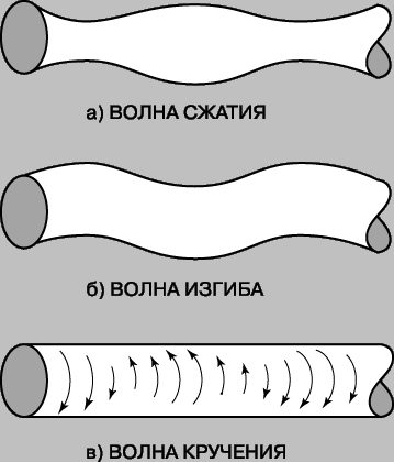
Two other types of waves are also possible in a rod - a bending wave (Fig. 3b) and a torsion wave (Fig. 3c). Bending deformations correspond to a wave that is neither purely longitudinal nor purely transverse. Torsion deformations, i.e. rotation around the axis of the rod, give a purely transverse wave. The speed of a bending wave in a rod depends on the wavelength. Such a wave is called "dispersive". The torsion waves in the rod are purely transverse and non-dispersive. Their speed is given by the formula
![]()
where m is the shear modulus characterizing the elastic properties of the material with respect to shear. Some typical shear wave velocities are given in Table 1. 1. Velocity in extended solid media. In solid media of large volume, where the influence of boundaries can be neglected, two types of elastic waves are possible: longitudinal and transverse. The deformation in a longitudinal wave is a plane deformation, i.e. one-dimensional compression (or rarefaction) in the direction of wave propagation. The deformation corresponding to a transverse wave is a shear displacement perpendicular to the direction of wave propagation. Speed longitudinal waves in solid materials is given by
![]()
where CL is the modulus of elasticity for simple plane deformation. It is related to the bulk modulus B (which is defined below) and the shear modulus m of the material as CL = B + 4/3m. In table. 1 shows the values of the velocities of longitudinal waves for various solid materials. The speed of shear waves in extended solid media is the same as the speed of torsion waves in a rod of the same material. Therefore, it is given by the expression. Its values for conventional solid materials are given in Table. one.
speed in gases. In gases, only one type of deformation is possible: compression - rarefaction. The corresponding elastic modulus B is called the bulk modulus. It is determined by the relation -DP = B(DV/V). Here DP is the change in pressure, DV/V is the relative change in volume. The minus sign indicates that as pressure increases, volume decreases. The value of B depends on whether or not the temperature of the gas changes during compression. In the case of a sound wave, it can be shown that the pressure changes very quickly and the heat released during compression does not have time to leave the system. Thus, the change in pressure in the sound wave occurs without heat exchange with the surrounding particles. Such a change is called adiabatic. It has been established that the speed of sound in a gas depends only on temperature. At a given temperature, the speed of sound is approximately the same for all gases. At a temperature of 21.1 ° C, the speed of sound in dry air is 344.4 m / s and increases with increasing temperature.
Velocity in liquids. Sound waves in liquids are waves of compression - rarefaction, as in gases. Speed is given by the same formula. However, a liquid is much less compressible than a gas, and therefore the value of B is many times greater for it, and the density r is also greater. The speed of sound in liquids is closer to the speed in solids than in gases. It is much smaller than in gases and depends on temperature. For example, the speed in fresh water is 1460 m/s at 15.6°C. sea water normal salinity at the same temperature is 1504 m/s. The speed of sound increases with increasing water temperature and salt concentration.
standing waves. When a harmonic wave is excited in a confined space so that it bounces off boundaries, so-called standing waves occur. A standing wave is the result of the superposition of two waves traveling one in a straight line and the other in a reverse direction. There is a pattern of oscillations that does not move in space, with alternating antinodes and nodes. At the antinodes, the deviations of the oscillating particles from their equilibrium positions are maximum, and at the nodes they are equal to zero.
Standing waves in a string. In a stretched string, transverse waves arise, and the string is displaced relative to its original, rectilinear position. When photographing waves in a string, the nodes and antinodes of the fundamental tone and overtones are clearly visible. The picture of standing waves greatly facilitates the analysis of oscillatory motions of a string of a given length. Let there be a string of length L fixed at the ends. Any kind of vibration of such a string can be represented as a combination of standing waves. Since the ends of the string are fixed, only such standing waves are possible that have nodes at the boundary points. The lowest frequency of vibration of a string corresponds to the maximum possible wavelength. Since the distance between nodes is l/2, the frequency is at its minimum when the string length is half the wavelength, i.e. for l = 2L. This is the so-called fundamental mode of string vibration. Its corresponding frequency, called the fundamental frequency or fundamental tone, is given by where v is the speed of the wave along the string. There is a whole sequence of oscillations of higher frequencies that correspond to standing waves with a large number of nodes. The next higher frequency, which is called the second harmonic or first overtone, is given by f = v/L. The sequence of harmonics is expressed by the formula f = nv/2L, where n = 1, 2, 3, etc. This is the so-called. eigenfrequencies of the string vibrations. They increase in proportion to the natural numbers: higher harmonics in 2, 3, 4...etc. times the fundamental frequency. Such a series of sounds is called the natural or harmonic scale. All this is of great importance in musical acoustics, which will be discussed in more detail below. For now, we note that the sound produced by a string contains all natural frequencies. The relative contribution of each of them depends on the point at which the vibrations of the string are excited. If, for example, a string is plucked in the middle, then the fundamental frequency will be most excited, since this point corresponds to the antinode. The second harmonic will be absent, since its node is located in the center. The same can be said about other harmonics (see below Musical acoustics). The speed of the waves in the string is
![]()
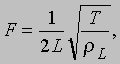
where T is the tension force of the string, and rL is the mass per unit length of the string. Therefore, the natural frequency spectrum of the string is given by

Thus, an increase in string tension leads to an increase in vibration frequencies. To lower the oscillation frequencies for a given T, one can take a heavier string (large rL) or increase its length.
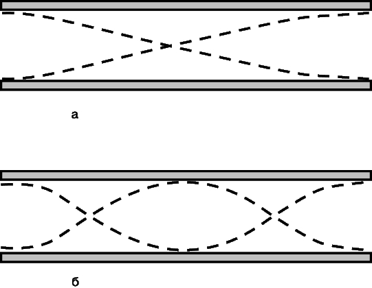
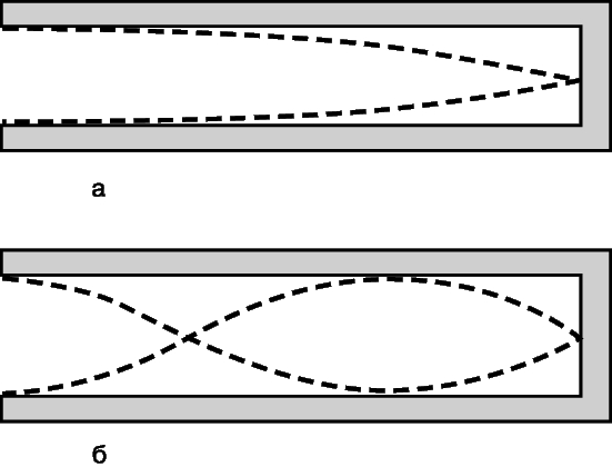
Standing waves in organ pipes. The theory stated in relation to a string can also be applied to air vibrations in an organ-type pipe. An organ pipe can be simplistically viewed as a straight pipe in which standing waves are excited. The pipe can have both closed and open ends. An antinode of a standing wave occurs at the open end, and a knot occurs at the closed end. Therefore, a pipe with two open ends has a fundamental frequency at which half the wavelength fits along the length of the pipe. A pipe, in which one end is open and the other is closed, has a fundamental frequency at which a quarter of the wavelength fits along the length of the pipe. Thus, the fundamental frequency for a pipe open at both ends is f = v/2L, and for a pipe open at one end, f = v/4L (where L is the length of the pipe). In the first case, the result is the same as for the string: the overtones are double, triple, and so on. value of the fundamental frequency. However, for a pipe open at one end, the overtones will be greater than the fundamental frequency by 3, 5, 7, etc. once. On fig. Figures 4 and 5 schematically show the standing waves of the fundamental frequency and the first overtone for the pipes of the two considered types. For reasons of convenience, the offsets are shown here as transverse, but in fact they are longitudinal.
resonant oscillations. Standing waves are closely related to the phenomenon of resonance. The natural frequencies discussed above are also the resonant frequencies of a string or organ pipe. Suppose that a loudspeaker is placed near the open end of the organ pipe, emitting a signal of one specific frequency, which can be changed at will. Then, if the frequency of the loudspeaker signal coincides with the main frequency of the pipe or with one of its overtones, the pipe will sound very loud. This is because the loudspeaker excites vibrations of the air column with a significant amplitude. The trumpet is said to resonate under these conditions.
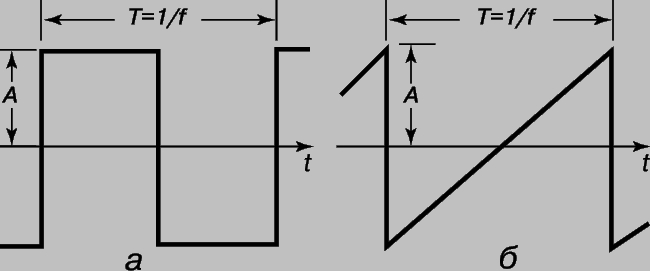
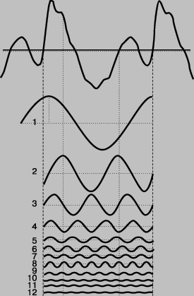
Fourier analysis and frequency spectrum of sound. In practice, sound waves of a single frequency are rare. But complex sound waves can be decomposed into harmonics. This method is called Fourier analysis after the French mathematician J. Fourier (1768-1830), who was the first to apply it (in the theory of heat). A graph of the relative energy of sound vibrations versus frequency is called the frequency spectrum of sound. There are two main types of such spectra: discrete and continuous. The discrete spectrum consists of separate lines for frequencies separated by empty spaces. All frequencies are present in the continuous spectrum within its band. Periodic sound vibrations. Sound vibrations are periodic if the oscillatory process, no matter how complex it may be, is repeated after a certain time interval. Its spectrum is always discrete and consists of harmonics of a certain frequency. Hence the term "harmonic analysis". An example is rectangular oscillations (Fig. 6, a) with a change in amplitude from +A to -A and a period T = 1/f. Another simple example is the triangular sawtooth oscillation shown in Fig. 6b. An example of periodic fluctuations over complex shape with the corresponding harmonic components is shown in fig. 7.
Musical sounds are periodic vibrations and therefore contain harmonics (overtones). We have already seen that in a string, along with oscillations of the fundamental frequency, other harmonics are excited to one degree or another. The relative contribution of each overtone depends on the way the string is excited. The set of overtones largely determines the timbre of the musical sound. These issues are discussed in more detail below in the section on musical acoustics.
The spectrum of a sound pulse. The usual variety of sound is the sound of short duration: clapping hands, knocking on the door, the sound of an object falling on the floor, cuckoo cuckooing. Such sounds are neither periodic nor musical. But they can also be decomposed into a frequency spectrum. In this case, the spectrum will be continuous: to describe the sound, all frequencies are needed within a certain band, which can be quite wide. Knowing such a frequency spectrum is necessary to reproduce such sounds without distortion, since the corresponding electronic system must "pass" all these frequencies equally well. The main features of a sound pulse can be clarified by considering a pulse of a simple form. Let us assume that the sound is an oscillation of duration Dt, at which the change in pressure is as shown in Fig. 8, a. An approximate frequency spectrum for this case is shown in Fig. 8b. The center frequency corresponds to the vibrations that we would have if the same signal were extended indefinitely.
![]()
Let us call the length of the frequency spectrum the bandwidth Df (Fig. 8b). Bandwidth is the approximate range of frequencies needed to reproduce the original pulse without excessive distortion. There is a very simple fundamental relation between Df and Dt, namely DfDt SOUND AND ACOUSTICS 1. This relation is true for all sound impulses. Its meaning is that the shorter the pulse, the more frequencies it contains. Let us assume that a sonar is used to detect a submarine, emitting ultrasound in the form of a pulse with a duration of 0.0005 s and a signal frequency of 30 kHz. The bandwidth is 1/0.0005 = 2 kHz, and the frequencies actually contained in the spectrum of the locator pulse lie in the range from 29 to 31 kHz.
Noise. Noise refers to any sound produced by multiple, uncoordinated sources. An example is the sound of tree leaves being swayed by the wind. Jet engine noise is due to the turbulence of the high-velocity exhaust stream.
Sound intensity. Sound volume may vary. It is easy to see that this is due to the energy carried by the sound wave. For quantitative comparisons of loudness, it is necessary to introduce the concept of sound intensity. The intensity of a sound wave is defined as the average energy flux through a unit area of the wave front per unit time. In other words, if we take a single area (for example, 1 cm2), which would completely absorb sound, and place it perpendicular to the direction of wave propagation, then the sound intensity is equal to the acoustic energy absorbed in one second. The intensity is usually expressed in W/cm2 (or W/m2). We give the value of this value for some familiar sounds. The amplitude of the overpressure that occurs during a normal conversation is approximately one millionth of atmospheric pressure, which corresponds to an acoustic sound intensity of the order of 10-9 W/cm2. The total power of the sound emitted during a normal conversation is on the order of only 0.00001 watts. The ability of the human ear to perceive such small energies testifies to its amazing sensitivity. The range of sound intensities perceived by our ear is very wide. The intensity of the loudest sound the ear can bear is about 1014 times the lowest it can hear. The full power of sound sources covers an equally wide range. So, the power emitted during a very quiet whisper can be on the order of 10-9 W, while the power emitted jet engine, reaches 105 watts. Again, the intensities differ by a factor of 10 14.
Decibel. Since sounds vary so much in intensity, it is more convenient to think of it as a logarithmic value and measure it in decibels. The logarithmic value of the intensity is the logarithm of the ratio of the considered value of the quantity to its value, taken as the original. The intensity level J with respect to some conditionally chosen intensity J0 is Sound intensity level = 10 lg (J/J0) dB. Thus, one sound that is 20 dB more intense than another is 100 times more intense. In the practice of acoustic measurements, it is customary to express the sound intensity in terms of the corresponding overpressure amplitude Pe. When the pressure is measured in decibels relative to some conventionally selected pressure P0, the so-called sound pressure level is obtained. Since the sound intensity is proportional to Pe2 and lg(Pe2) = 2lgPe, the sound pressure level is defined as follows: Sound pressure level = 20 lg (Pe/P0) dB. Conditional pressure Р0 = 2*10-5 Pa corresponds to the standard hearing threshold for sound with a frequency of 1 kHz. In table. 2 shows sound pressure levels for some common sound sources. These are integral values obtained by averaging over the entire audible frequency range. Table 2.
TYPICAL SOUND PRESSURE LEVELS
Sound source Sound pressure level, dB (rel. 2*10-5 Pa)
Stamping shop ____________________________125
Engine room on board _________________115
Spinning and weaving shop _______________________105
In the subway car _______________________________95
In a car while driving in traffic 85
Typing Bureau ____________________________78
Accounting __________________________________63
Office ___________________________________________50
Living quarters ________________________________43
The territory of a residential area at night _______________35
Broadcasting studio ________________________________25
Volume. The sound pressure level is not associated with a simple relationship with the psychological perception of loudness. The first of these factors is objective, and the second is subjective. Experiments show that the perception of loudness depends not only on the intensity of the sound, but also on its frequency and experimental conditions. The volumes of sounds that are not tied to the conditions of comparison cannot be compared. Still, the comparison of pure tones is of interest. To do this, determine the sound pressure level at which a given tone is perceived as equally loud as a standard tone with a frequency of 1000 Hz. On fig. 9 shows equal loudness curves obtained in the experiments of Fletcher and Manson. For each curve, the corresponding sound pressure level of a standard tone of 1000 Hz is indicated. For example, at a tone frequency of 200 Hz, a sound level of 60 dB is needed to be perceived as equal to a tone of 1000 Hz with a sound pressure level of 50 dB.
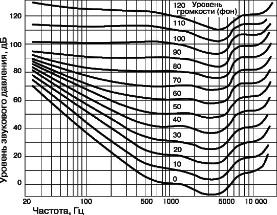
These curves are used to define hum, a unit of loudness that is also measured in decibels. The background is the sound volume level for which the sound pressure level of an equally loud standard pure tone (1000 Hz) is 1 dB. So, a sound with a frequency of 200 Hz at a level of 60 dB has a volume level of 50 phons. The lower curve in fig. 9 is the hearing threshold curve of a good ear. The range of audible frequencies extends from about 20 to 20,000 Hz (see also HEARING).
Propagation of sound waves. Like the waves from a pebble thrown into still water, sound waves propagate in all directions. It is convenient to characterize such a propagation process as a wave front. A wave front is a surface in space, at all points of which oscillations occur in one phase. Wave fronts from a pebble that has fallen into the water are circles.
Flat waves. The wave front of the simplest form is flat. A plane wave propagates in only one direction and is an idealization that is only approximately realized in practice. A sound wave in a pipe can be considered approximately flat, just like a spherical wave at a great distance from the source.
spherical waves. Simple types of waves include a wave with a spherical front, emanating from a point and propagating in all directions. Such a wave can be excited using a small pulsating sphere. A source that excites a spherical wave is called a point source. The intensity of such a wave decreases as it propagates, as the energy is distributed over a sphere of ever larger radius. If a point source producing a spherical wave emits a power of 4pQ, then since the surface area of a sphere of radius r is 4pr2, the sound intensity in the spherical wave is J = Q/r2, where r is the distance from the source. Thus, the intensity of a spherical wave decreases inversely with the square of the distance from the source. The intensity of any sound wave during its propagation decreases due to the absorption of sound. This phenomenon will be discussed below.
Huygens principle. The Huygens principle is valid for wave front propagation. To clarify it, let us consider the shape of the wave front known to us at some point in time. It can also be found after the time Dt, if each point of the initial wave front is considered as a source of an elementary spherical wave propagating over this interval to a distance vDt. The envelope of all these elementary spherical wave fronts will be the new wave front. Huygens' principle makes it possible to determine the shape of the wavefront throughout the propagation process. It also implies that waves, both plane and spherical, retain their geometry during propagation, provided that the medium is homogeneous.
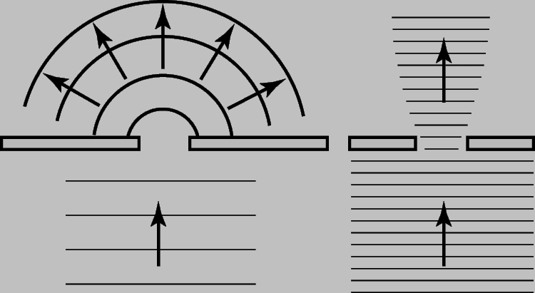
sound diffraction. Diffraction is the wave bending around an obstacle. Diffraction is analyzed using the Huygens principle. The degree of this bending depends on the relationship between the wavelength and the size of the obstacle or hole. Since the wavelength of a sound wave is many times longer than that of light, the diffraction of sound waves surprises us less than the diffraction of light. So, you can talk to someone standing around the corner of the building, although he is not visible. The sound wave easily bends around the corner, while the light, due to the smallness of its wavelength, creates sharp shadows. Consider the diffraction of a plane sound wave incident on a solid flat screen with a hole. To determine the shape of the wavefront on the other side of the screen, you need to know the ratio between the wavelength l and the hole diameter D. If these values are approximately the same or l is much larger than D, then complete diffraction is obtained: the wavefront of the outgoing wave will be spherical, and the wave will reach all points beyond screen. If l is somewhat less than D, then the outgoing wave will propagate predominantly in the forward direction. And finally, if l is much less than D, then all of its energy will propagate in a straight line. These cases are shown in Fig. ten.
Diffraction is also observed when there is an obstacle in the path of sound. If the dimensions of the obstacle are much larger than the wavelength, then the sound is reflected, and an acoustic shadow zone is formed behind the obstacle. When the size of the obstacle is comparable to or less than the wavelength, the sound diffracts to some extent in all directions. This is taken into account in architectural acoustics. So, for example, sometimes the walls of a building are covered with protrusions with dimensions of the order of the wavelength of sound. (At a frequency of 100 Hz, the wavelength in air is about 3.5 m.) In this case, the sound, falling on the walls, is scattered in all directions. In architectural acoustics, this phenomenon is called sound diffusion.
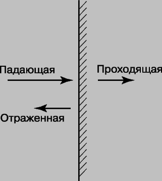
Reflection and transmission of sound. When a sound wave traveling in one medium is incident on an interface with another medium, three processes can occur simultaneously. The wave can be reflected from the interface, it can pass into another medium without changing direction, or it can change direction at the interface, i.e. refract. On fig. 11 shown simplest case when a plane wave is incident at right angles to a flat surface separating two various substances. If the intensity reflection coefficient, which determines the fraction of the reflected energy, is equal to R, then the transmission coefficient will be equal to T = 1 - R.
For a sound wave, the ratio of excess pressure to vibrational volumetric velocity is called acoustic impedance. The reflection and transmission coefficients depend on the ratio of the wave impedances of the two media, the wave impedances, in turn, are proportional to the acoustic impedances. The wave resistance of gases is much less than that of liquids and solids. So if a wave in the air hits a thick solid object or the surface of deep water, the sound is almost completely reflected. For example, for the boundary of air and water, the ratio of wave resistances is 0.0003. Accordingly, the energy of sound passing from air into water is equal to only 0.12% of the incident energy. The reflection and transmission coefficients are reversible: the reflection coefficient is the transmission coefficient in the opposite direction. Thus, sound practically does not penetrate either from the air into the water basin, or from under the water to the outside, which is well known to everyone who swam under water. In the case of reflection considered above, it was assumed that the thickness of the second medium in the direction of wave propagation is large. But the transmission coefficient will be significantly greater if the second medium is a wall separating two identical media, such as a solid partition between rooms. The fact is that the wall thickness is usually less than the wavelength of sound or comparable to it. If the wall thickness is a multiple of half the wavelength of sound in the wall, then the transmission coefficient of the wave at perpendicular incidence is very large. The baffle would be absolutely transparent to the sound of this frequency if it were not for absorption, which we neglect here. If the wall thickness is much less than the wavelength of sound in it, then the reflection is always small, and the transmission is large, unless special measures are taken to increase the absorption of sound.
refraction of sound. When a plane sound wave is incident at an angle on an interface, the angle of its reflection is equal to the angle of incidence. The transmitted wave deviates from the direction of the incident wave if the angle of incidence is different from 90°. This change in the direction of the wave is called refraction. The geometry of refraction at a flat boundary is shown in Fig. . 12. The angles between the direction of the waves and the normal to the surface are denoted by q1 for an incident wave and q2 for a refracted transmitted one. The relation between these two angles includes only the ratio of the speeds of sound for the two media. As in the case of light waves, these angles are related to each other by the Snell (Snell) law:
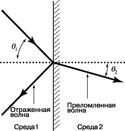

Thus, if the speed of sound in the second medium is less than in the first, then the angle of refraction will be less than the angle of incidence; if the speed in the second medium is greater, then the angle of refraction will be greater than the angle of incidence. Refraction due to temperature gradient. If the speed of sound in an inhomogeneous medium changes continuously from point to point, then the refraction also changes. Since the speed of sound in both air and water depends on temperature, in the presence of a temperature gradient, sound waves can change their direction of movement. In the atmosphere and ocean, due to horizontal stratification, vertical temperature gradients are commonly observed. Therefore, due to changes in the speed of sound along the vertical, due to temperature gradients, the sound wave can be deflected either up or down. Let us consider the case when the air is warmer in some place near the Earth's surface than in the higher layers. Then, as the altitude increases, the air temperature here decreases, and with it, the speed of sound also decreases. Sound emitted by a source near the surface of the Earth will go up due to refraction. This is shown in fig. 13, which shows sound "beams".

The deflection of the sound rays shown in fig. 13 is generally described by Snell's law. If q, as before, denotes the angle between the vertical and the direction of radiation, then the generalized Snell's law has the form of the equality sinq/v = const, referring to any point of the beam. Thus, if the beam passes into a region where the speed v decreases, then the angle q must also decrease. Therefore, sound beams are always deflected in the direction of decreasing sound speed. From fig. 13 it can be seen that there is a region located at some distance from the source, where sound rays do not penetrate at all. This is the so-called zone of silence. It is quite possible that somewhere at a height greater than that shown in Fig. 13, due to the temperature gradient, the speed of sound increases with height. In this case, the initially deviated upward sound wave will deviate here to the Earth's surface at a great distance. This happens when a layer of temperature inversion forms in the atmosphere, as a result of which it becomes possible to receive ultra-long-range sound signals. At the same time, the reception quality at remote points is even better than near. There have been many examples of ultra-long-range reception in history. For example, during the First World War, when atmospheric conditions favored appropriate sound refraction, cannonades on the French front could be heard in England.
Refraction of sound under water. Sound refraction due to vertical temperature changes is also observed in the ocean. If the temperature, and therefore the speed of sound, decreases with depth, the sound rays are deflected downward, resulting in a zone of silence similar to that shown in Fig. 13 for atmosphere. For the ocean, the corresponding picture will turn out if this picture is simply turned over
(see also SONAR). The presence of silence zones makes it difficult to detect submarines with sonar, and refraction, which deflects sound waves downward, significantly limits their propagation range near the surface. However, upward deflection is also observed. It can create more favorable conditions for sonar.
Interference of sound waves. superposition of two or more waves is called wave interference. Standing waves as a result of interference. The above standing waves - special case interference. Standing waves are formed as a result of the superposition of two waves of the same amplitude, phase and frequency, propagating in opposite directions.
Amplitude at antinodes of a standing wave
is equal to twice the amplitude of each of the waves. Since the intensity of the wave is proportional to the square of its amplitude, this means that the intensity at the antinodes is 4 times greater than the intensity of each of the waves, or 2 times greater than the total intensity of the two waves. There is no violation of the law of conservation of energy here, since at the nodes the intensity is zero.
beats. Interference of harmonic waves of different frequencies is also possible. When two frequencies differ little, so-called beats occur. Beats are changes in the amplitude of sound that occur at a frequency equal to the difference in the original frequencies. On fig. 14 shows the beat waveform.
It should be borne in mind that the beat frequency is the frequency of the amplitude modulation of the sound. Also, beats should not be confused with the difference frequency resulting from the distortion of a harmonic signal. Beats are often used when tuning two tones in unison. The frequency is adjusted until the beats are no longer audible. Even if the beat frequency is very low, the human ear is able to pick up the periodic rise and fall in the volume of the sound. Therefore, beats are a very sensitive tuning method in the audio range. If the setting is not accurate, then the frequency difference can be determined by ear by counting the number of beats in one second. In music, beats of higher harmonic components are also perceived by ear, which is used when tuning the piano
(see also DOPPLER EFFECT). Absorption of sound waves. The intensity of sound waves in the process of their propagation always decreases due to the fact that a certain part of the acoustic energy is scattered. Due to the processes of heat transfer, intermolecular interaction and internal friction, sound waves are absorbed in any medium. The intensity of absorption depends on the frequency of the sound wave and on other factors such as pressure and temperature of the medium. The absorption of a wave in a medium is quantitatively characterized by the absorption coefficient a. It shows how quickly the excess pressure decreases depending on the distance traveled by the propagating wave. The decrease in the amplitude of overpressure -DPe when passing the distance Dx is proportional to the amplitude of the initial overpressure Pe and the distance Dx. So -DPe = aPeDx. For example, when we say that the absorption loss is 1 dB/m, this means that at a distance of 50 m the sound pressure level is reduced by 50 dB. Absorption due to internal friction and heat conduction. During the movement of particles associated with the propagation of a sound wave, friction between different particles of the medium is inevitable. In liquids and gases, this friction is called viscosity. Viscosity, which determines the irreversible conversion of acoustic wave energy into heat, is main reason sound absorption in gases and liquids. In addition, absorption in gases and liquids is due to heat loss during compression in the wave. We have already said that during the passage of the wave, the gas in the compression phase heats up. In this fast-flowing process, heat usually does not have time to be transferred to other regions of the gas or to the walls of the vessel. But in reality, this process is not ideal, and part of the released thermal energy leaves the system. Associated with this is sound absorption due to heat conduction. Such absorption occurs in compression waves in gases, liquids and solids. Sound absorption, due to both viscosity and thermal conductivity, generally increases with the square of the frequency. Thus, high frequency sounds are absorbed much more strongly than low frequency sounds. For example, at normal pressure and temperature, the absorption coefficient (due to both mechanisms) at a frequency of 5 kHz in air is about 3 dB/km. Since the absorption is proportional to the square of the frequency, the absorption coefficient at 50 kHz is 300 dB/km.
Absorption in solids. The mechanism of sound absorption due to thermal conductivity and viscosity, which takes place in gases and liquids, is also preserved in solids. However, here new absorption mechanisms are added to it. They are associated with defects in the structure of solids. The point is that polycrystalline solid materials consist of small crystallites; when sound passes through them, deformations occur, leading to the absorption of sound energy. Sound is also scattered at the boundaries of crystallites. In addition, even single crystals contain dislocation-type defects that contribute to sound absorption. Dislocations are violations of the coordination of atomic planes. When the sound wave causes the atoms to vibrate, the dislocations move and then return to their original position, dissipating energy due to internal friction. Absorption due to dislocations explains, in particular, why the lead bell does not ring. Lead is a soft metal, which has a lot of dislocations, and therefore sound vibrations in it decay extremely quickly. But it will ring well if it is cooled with liquid air. At low temperatures, dislocations are "frozen" in a fixed position, and therefore do not move and do not transform sound energy into warmth.
MUSICAL ACOUSTICS
Musical sounds. Musical acoustics studies the features of musical sounds, their characteristics related to how we perceive them, and the mechanisms of the sound of musical instruments. Musical sound or tone is a periodic sound, i.e. fluctuations that repeat over and over again after a certain period. It was said above that a periodic sound can be represented as a sum of oscillations with frequencies that are multiples of the fundamental frequency f: 2f, 3f, 4f, etc. It was also noted that vibrating strings and columns of air emit musical sounds. Musical sounds are distinguished by three characteristics: loudness, pitch and timbre. All these indicators are subjective, but they can be associated with the measured values. Loudness is related mainly to the intensity of the sound; the pitch of the sound, which characterizes its position in the musical system, is determined by the frequency of the tone; the timbre, by which one instrument or voice differs from another, is characterized by the distribution of energy over the harmonics and the change in this distribution over time.
Sound pitch. The pitch of a musical sound is closely related to the frequency, but not identical to it, since the assessment of the pitch is subjective. So, for example, it was found that the estimate of the pitch of a single-frequency sound somewhat depends on the level of its loudness. With a significant increase in volume, say 40 dB, the apparent frequency can decrease by 10%. In practice, this dependence on loudness does not matter, since musical sounds are much more complex than single-frequency sound. On the question of the relationship between pitch and frequency, something else is more significant: if musical sounds are made up of harmonics, then with what frequency is the perceived pitch associated? It turns out that this may not be the frequency that corresponds to the maximum energy, and not the lowest frequency in the spectrum. So, for example, a musical sound consisting of a set of frequencies of 200, 300, 400 and 500 Hz is perceived as a sound with a height of 100 Hz. That is, the pitch is associated with the fundamental frequency of the harmonic series, even if it is not in the spectrum of the sound. True, most often the fundamental frequency is present to some extent in the spectrum. Speaking about the relationship between the pitch and its frequency, one should not forget about the features of the human hearing organ. This is a special acoustic receiver that introduces its own distortions (not to mention the fact that there are psychological and subjective aspects of hearing). The ear is able to select some frequencies, in addition, the sound wave undergoes non-linear distortions in it. Frequency selectivity is due to the difference between the loudness of the sound and its intensity (Fig. 9). It is more difficult to explain non-linear distortions, which are expressed in the appearance of frequencies that are absent in the original signal. The non-linearity of the ear reaction is due to the asymmetry of the movement of its various elements. One of characteristic features of a nonlinear receiving system is that when it is excited by sound with a frequency f1, harmonic overtones 2f1, 3f1, ..., and in some cases subharmonics of the 1/2 f1 type are excited in it. In addition, when a nonlinear system is excited by two frequencies f1 and f2, the sum and difference frequencies f1 + f2 and f1 - f2 are excited in it. The greater the amplitude of the initial oscillations, the greater the contribution of "extra" frequencies. Thus, due to the non-linearity of the acoustic characteristics of the ear, frequencies that are absent in the sound may appear. Such frequencies are called subjective tones. Let's assume that the sound consists of pure tones with frequencies of 200 and 250 Hz. Due to the non-linearity of the response, additional frequencies will appear 250 - 200 = 50, 250 + 200 = 450, 2*200 = 400, 2*250 = 500 Hz, etc. It will seem to the listener that there is a whole set of combination frequencies in the sound, but their appearance is actually due to the non-linear response of the ear. When a musical sound consists of a fundamental frequency and its harmonics, it is obvious that the fundamental frequency is effectively amplified by the difference frequencies. True, studies have shown that subjective frequencies arise only at a sufficiently large amplitude of the original signal. Therefore, it is possible that in the past the role of subjective frequencies in music was greatly exaggerated.
Musical standards and measuring the pitch of musical sound. In the history of music, sounds of different frequencies were taken as the main tone, which determines the entire musical structure. Now the generally accepted frequency for the note "la" of the first octave is 440 Hz. But in the past it has changed from 400 to 462 Hz. The traditional way to determine the pitch of a sound is to compare it to the tone of a standard tuning fork. The deviation of the frequency of a given sound from the standard is judged by the presence of beats. Tuning forks are still used today, although now there are more convenient devices for determining the pitch, such as a stable frequency reference oscillator (with a quartz resonator), which can be smoothly tuned within the entire sound range. True, the exact calibration of such a device is quite difficult. A widely used stroboscopic method of measuring pitch, in which the sound musical instrument sets the flash rate of the strobe lamp. The lamp illuminates a pattern on a disk rotating at a known frequency, and the fundamental frequency of the tone is determined from the apparent frequency of movement of the pattern on the disk under stroboscopic illumination. The ear is very sensitive to pitch change, but its sensitivity depends on the frequency. It is maximum near the lower threshold of audibility. Even an untrained ear can detect only 0.3% difference in frequencies between 500 and 5000 Hz. Sensitivity can be increased by training. Musicians have a very developed sense of pitch, but this does not always help in determining the frequency of the pure tone produced by the reference oscillator. This suggests that when determining the frequency of a sound by ear, its timbre plays an important role.
Timbre. Timbre refers to those features of musical sounds that give musical instruments and voices their unique specificity, even if we compare sounds of the same pitch and loudness. This is, so to speak, the sound quality. The timbre depends on the frequency spectrum of the sound and its change over time. It is determined by several factors: the distribution of energy over overtones, the frequencies that occur at the moment the sound appears or stops (the so-called transitional tones) and their decay, as well as the slow amplitude and frequency modulation of the sound ("vibrato"). overtone intensity. Consider a stretched string, which is excited by a pinch in its middle part (Fig. 15a). Since all even harmonics have nodes in the middle, they will be absent, and the oscillations will consist of odd harmonics of the fundamental frequency equal to f1 = v/2l, where v is the speed of the wave in the string, and l is its length. Thus, only the frequencies f1, 3f1, 5f1, etc. will be present. The relative amplitudes of these harmonics are shown in Figs. 15b.
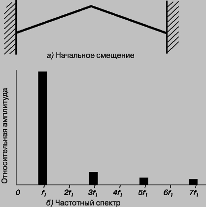
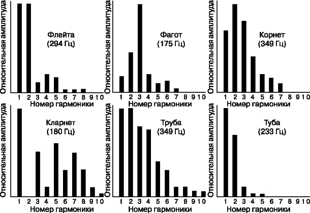
This example allows us to draw the following important general conclusion. The set of harmonics of a resonant system is determined by its configuration, and the distribution of energy over harmonics depends on the method of excitation. When the string is excited in its middle, the fundamental frequency dominates and the even harmonics are completely suppressed. If the string is fixed in its middle part and plucked in some other place, then the fundamental frequency and odd harmonics will be suppressed. All of this applies to other well-known musical instruments, although the details can be very different. Instruments usually have an air cavity, soundboard, or horn to emit sound. All this determines the structure of overtones and the appearance of formants. On fig. 16 shows the waveforms for various instruments and voices, and fig. 17 shows some frequency spectra for sustained tones of various common instruments.
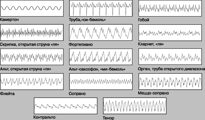
Rice. 16. Oscillograms of vibrations corresponding to the note "la" taken on different instruments and in different voices.
Formants. As mentioned above, the sound quality of musical instruments depends on the distribution of energy among the harmonics. When changing the pitch of many instruments, and especially the human voice, the distribution of harmonics changes so that the main overtones are always located in approximately the same frequency range, which is called the formant range. One of the reasons for the existence of formants is the use of resonant elements to amplify sound, such as soundboards and air resonators. The width of natural resonances is usually large, due to which the radiation efficiency at the corresponding frequencies is higher. For brass instruments, the formants are determined by the bell from which the sound is emitted. The overtones that fall within the formant range are always strongly emphasized, since they are emitted with maximum energy. Formants largely determine the characteristic qualitative features of the sounds of a musical instrument or voice.
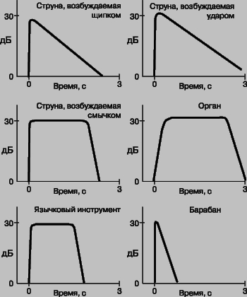
Changing tones over time. The tone of the sound of any instrument rarely remains constant over time, and timbre is essentially related to this. Even when the instrument sustains a long note, there is a slight periodic modulation of frequency and amplitude, enriching the sound - "vibrato". This is especially true for stringed instruments such as the violin and for the human voice. For many instruments, such as the piano, the duration of the sound is such that a constant tone does not have time to form - the excited sound quickly increases, and then its rapid decay follows. Since the decay of overtones is usually due to frequency-dependent effects (such as acoustic radiation), it is clear that the overtone distribution changes over the course of a tone. The nature of the change in tone over time (the rate of rise and fall of the sound) for some instruments is schematically shown in Fig. 18. As you can see, stringed instruments (plucked and keyboards) have almost no constant tone. In such cases, it is possible to speak about the spectrum of overtones only conditionally, since the sound changes rapidly in time. The rise and fall characteristics are also an important part of the timbre of these instruments.
transitional tones. The harmonic composition of a tone usually changes rapidly in a short time after sound excitation. In those instruments in which the sound is excited by striking the strings or plucking, the energy attributable to higher harmonics (as well as to numerous non-harmonic components) is maximum immediately after the sound begins, and after a fraction of a second these frequencies fade. Such sounds, called transitional, give a specific coloring to the sound of the instrument. In the piano, they are caused by the action of the hammer striking the string. Sometimes musical instruments with the same overtone structure can only be distinguished by transitional tones.
THE SOUND OF MUSICAL INSTRUMENTS
Musical sounds can be excited and changed in many ways, and therefore musical instruments are distinguished by a variety of forms. Instruments were mostly created and improved by the musicians themselves and by skilled craftsmen who did not resort to scientific theory. Therefore, acoustic science cannot explain, for example, why a violin has such a shape. However, it is quite possible to describe the sound properties of a violin in terms of the general principles of its playing and its construction. The frequency range of an instrument is usually understood as the frequency range of its fundamental tones. The human voice spans approximately two octaves, while a musical instrument spans at least three (a large organ spans ten). In most cases, the overtones extend to the very edge of the audible sound range. Musical instruments have three main parts: an oscillating element, a mechanism for its excitation, and an auxiliary resonator (horn or soundboard) for acoustic communication between the oscillating element and the surrounding air. Musical sound is periodic in time, and periodic sounds are composed of a series of harmonics. Since the natural frequencies of the vibrations of strings and air columns of fixed length are harmonically related, in many instruments the main vibrating elements are strings and air columns. With a few exceptions (the flute is one of them), single-frequency sounds cannot be taken on instruments. When the main vibrator is excited, a sound containing overtones arises. Some vibrators resonant frequencies are not harmonic components. Instruments of this kind (for example, drums and cymbals) are used in orchestral music for special expressiveness and emphasis on rhythm, but not for melodic development.
Stringed instruments. By itself, a vibrating string is a poor emitter of sound, and therefore a stringed instrument must have an additional resonator to excite sound of noticeable intensity. It can be a closed volume of air, a deck, or a combination of both. The nature of the sound of the instrument is also determined by the way the strings are excited. We saw earlier that the fundamental vibration frequency of a fixed string of length L is given by
where T is the tension force of the string, and rL is the mass per unit length of the string. Therefore, we can change the frequency in three ways: by changing the length, tension, or mass. Many instruments use a small number of strings of the same length, the fundamental frequencies of which are determined by the proper choice of tension and mass. Other frequencies are obtained by shortening the length of the string with your fingers. Other instruments, such as the piano, have one of many pre-tuned strings for each note. Tuning a piano where the frequency range is large is not an easy task, especially in the low frequency region. The tension force of all piano strings is almost the same (about 2 kN), and the variety of frequencies is achieved by changing the length and thickness of the strings. A stringed instrument can be excited by a pluck (for example, on a harp or banjo), a blow (on a piano), or with a bow (in the case of musical instruments of the violin family). In all cases, as shown above, the number of harmonics and their amplitude depend on the way the string is excited.
piano. A typical example of an instrument where the excitation of a string is produced by a blow is the pianoforte. The large soundboard of the instrument provides a wide range of formants, so its timbre is very uniform for any excited note. The maxima of the main formants occur at frequencies of the order of 400-500 Hz, and at lower frequencies the tones are especially rich in harmonics, and the amplitude of the fundamental frequency is less than that of some overtones. In the piano, the hammer strike on all but the shortest strings falls on a point located 1/7 of the length of the string from one of its ends. This is usually explained by the fact that in this case the seventh harmonic, which is dissonant with respect to the fundamental frequency, is significantly suppressed. But due to the finite width of the malleus, other harmonics located near the seventh are also suppressed.
Violin family. In the violin family of instruments, long sounds are produced by a bow, which applies a variable driving force to the string, which keeps the string vibrating. Under the action of a moving bow, the string is pulled to the side due to friction until it breaks due to an increase in the tension force. Returning to its original position, it is again carried away by the bow. This process is repeated, so that the string is subjected to a periodic external force. In order of increasing size and decreasing frequency range, the main bowed string instruments are arranged as follows: violin, viola, cello, double bass. The frequency spectra of these instruments are especially rich in overtones, which undoubtedly gives a special warmth and expressiveness to their sound. In the violin family, the vibrating string is acoustically connected to the air cavity and the body of the instrument, which mainly determine the structure of the formants, which occupy a very wide frequency range. Large representatives of the violin family have a set of formants shifted towards low frequencies. Therefore, the same note taken on two instruments of the violin family acquires a different timbre coloration due to the difference in the structure of the overtones. The violin has a pronounced resonance near 500 Hz, due to the shape of its body. When a note close to this frequency is played, an unwanted vibrating sound called "wolf tone" can be produced. The air cavity inside the violin body also has its own resonant frequencies, the main of which is located near 400 Hz. Due to its special shape, the violin has numerous closely spaced resonances. All of them, except for the wolf tone, do not really stand out in the general spectrum of the extracted sound.
Wind instruments. Woodwind instruments. Natural vibrations of air in a cylindrical pipe of finite length were discussed earlier. Natural frequencies form a series of harmonics, the fundamental frequency of which is inversely proportional to the length of the pipe. Musical sounds in wind instruments arise due to the resonant excitation of the air column. Air vibrations are excited either by vibrations in the air jet falling on the sharp edge of the resonator wall, or by vibrations of the flexible surface of the tongue in the air flow. In both cases, periodic pressure changes occur in a localized area of the tool barrel. The first of these methods of excitation is based on the occurrence of "edge tones". When a stream of air comes out of the slot, broken by a wedge-shaped obstacle with a sharp edge, vortices periodically appear - first on one side, then on the other side of the wedge. The frequency of their formation is greater, the greater the speed of the air flow. If such a device is acoustically coupled to a resonating air column, then the edge tone frequency is "captured" by the resonant frequency of the air column, i.e. the frequency of vortex formation is determined by the air column. Under such conditions, the main frequency of the air column is excited only when the air flow velocity exceeds a certain minimum value. In a certain range of speeds exceeding this value, the frequency of the edge tone is equal to this fundamental frequency. At an even higher air flow velocity (near the one at which the edge frequency in the absence of communication with the resonator would be equal to the second harmonic of the resonator), the edge frequency doubles abruptly and the pitch emitted by the entire system turns out to be an octave higher. This is called overflow. Edge tones excite air columns in instruments such as the organ, flute, and piccolo. When playing the flute, the performer excites the edge tones by blowing from the side into a side hole near one of the ends. Notes of one octave, starting from "D" and above, are obtained by changing the effective length of the barrel, opening the side holes, with a normal edge tone. Higher octaves are overblown. Another way to excite the sound of a wind instrument is based on the periodic interruption of the air flow by an oscillating tongue, which is called a reed, since it is made of reeds. This method is used in various woodwind and brass instruments. There are options with a single reed (as, for example, in the clarinet, saxophone and accordion-type instruments) and with a symmetrical double reed (as, for example, in the oboe and bassoon). In both cases, the oscillatory process is the same: air is blown through a narrow gap, in which the pressure decreases in accordance with Bernoulli's law. At the same time, the cane is drawn into the gap and covers it. In the absence of flow, the elastic cane straightens and the process is repeated. In wind instruments, the selection of the notes of the scale, as on the flute, is carried out by opening the side holes and overblow. Unlike a pipe that is open at both ends, which has a full range of overtones, a pipe that is open at only one end has only odd harmonics (see above). This is the configuration of the clarinet, and therefore even harmonics are weakly expressed in it. Overblowing in the clarinet occurs at a frequency 3 times higher than the main one. In the oboe, the second harmonic is quite intense. It differs from the clarinet in that its bore has a conical shape, while in the clarinet the cross section of the bore is constant over most of its length. The frequencies in a conical barrel are more difficult to calculate than in a cylindrical pipe, but there is still a full range of overtones. In this case, the oscillation frequencies of a conical tube with a closed narrow end are the same as those of a cylindrical tube open at both ends.
Brass wind instruments. Brass, including horn, trumpet, cornet-a-piston, trombone, horn and tuba, are excited by the lips, the action of which, in combination with a specially shaped mouthpiece, is similar to that of a double reed. The air pressure during sound excitation is much higher here than in woodwinds. Brass wind instruments, as a rule, are a metal barrel with cylindrical and conical sections, ending with a bell. The sections are selected so that the full range of harmonics is provided. The total length of the barrel ranges from 1.8 m for the pipe to 5.5 m for the tuba. The tuba is snail-shaped for ease of handling, not for acoustic reasons. With a fixed length of the barrel, the performer has only notes determined by the natural frequencies of the barrel (moreover, the fundamental frequency is usually "untaken"), and higher harmonics are excited by an increase in air pressure in the mouthpiece. Thus, only a few notes (second, third, fourth, fifth and sixth harmonics) can be played on a fixed-length bugle. On other brass instruments, the frequencies lying between the harmonics are taken with a change in barrel length. The trombone is unique in this sense, the length of the barrel of which is regulated by the smooth movement of the retractable U-shaped wings. Enumeration of notes of the entire scale is provided by seven different positions of the wings with a change in the excited overtone of the trunk. In other brass instruments, this is achieved by effectively increasing the overall length of the barrel with three lateral channels of different lengths and in different combinations. This gives seven different barrel lengths. As with the trombone, the notes of the entire scale are played by excitation of different series of overtones corresponding to these seven stem lengths.
The tones of all brass instruments are rich in harmonics. This is mainly due to the presence of a bell, which increases the efficiency of sound emission at high frequencies. The trumpet and horn are designed to play a much wider range of harmonics than the bugle. The part of the solo trumpet in the works of I. Bach contains many passages in the fourth octave of the series, reaching the 21st harmonic of this instrument.
Percussion instruments. Percussion instruments make sound by striking the body of the instrument and thereby exciting its free vibrations. From the piano, in which vibrations are also excited by a blow, such instruments differ in two respects: a vibrating body does not give harmonic overtones, and it itself can radiate sound without an additional resonator. Percussion instruments include drums, cymbals, xylophone and triangle. The oscillations of solids are much more complex than those of an air resonator of the same shape, since there are more types of oscillations in solids. So, waves of compression, bending and torsion can propagate along a metal rod. Therefore, a cylindrical rod has many more vibration modes and, therefore, resonant frequencies than a cylindrical air column. In addition, these resonant frequencies do not form a harmonic series. The xylophone uses the bending vibrations of solid bars. The overtone ratios of the vibrating xylophone bar to the fundamental frequency are: 2.76, 5.4, 8.9 and 13.3. A tuning fork is an oscillating curved rod, and its main type of oscillation occurs when both arms simultaneously approach each other or move away from each other. The tuning fork has no harmonic series of overtones, and only its fundamental frequency is used. The frequency of its first overtone is more than 6 times the fundamental frequency. Another example of hesitant solid body that makes musical sounds is a bell. The sizes of bells can be different - from a small bell to multi-ton church bells. The larger the bell, the lower the sounds it makes. The shape and other features of the bells have undergone many changes in the course of their centuries-old evolution. Very few enterprises are engaged in their manufacture, which requires great skill. The initial overtone series of the bell is not harmonic, and the overtone ratios are not the same for different bells. So, for example, for one large bell, the measured ratios of overtone frequencies to the fundamental frequency were 1.65, 2.10, 3.00, 3.54, 4.97 and 5.33. But the distribution of energy over the overtones changes rapidly immediately after the bell is struck, and the shape of the bell seems to be chosen in such a way that the dominant frequencies are related to each other approximately harmonically. The pitch of the bell is determined not by the fundamental frequency, but by the note that is dominant immediately after the strike. It corresponds approximately to the fifth overtone of the bell. After some time, the lower overtones begin to predominate in the sound of the bell. In the drum, the vibrating element is a leather membrane, usually round, which can be considered as a two-dimensional analogue of a stretched string. In music, the drum is not as important as the string, because its natural set of natural frequencies is not harmonic. The exception is the timpani, the membrane of which is stretched over an air resonator. The drum overtone sequence can be made harmonic by changing the thickness of the head in the radial direction. An example of such a drum is the tabla used in classical Indian music.
See - the acoustics section, in which the character of sound propagation is studied. waves, their emission and reception in a moving medium or when a sound source or receiver is in motion. The atmosphere, as well as the water in the seas and oceans, which is in constant motion, all this ... ... Physical Encyclopedia
ACOUSTICS- (from the Greek akouo I listen), the doctrine of sound, one of the oldest and most developed branches of physics. Acoustics can be divided into 1) general, 2) physiological, 3) atmospheric, 4) architectural, 5) musical. General acoustics studies the processes ... ...
The smallest structural element of music. Compared with all audible non-musical sounds, it has a number of features that are determined by the device of the hearing organ, the communicative nature of the muses. art and aesthetic requests of musicians and ... ... Music Encyclopedia
SOUND- is nothing else than vibrations of an elastic body, perceived by our ear with the help of some mediating medium (air). The three and used in music are called tones. Sometimes both words are used in a special sense; say for example: ... ... Riemann's musical dictionary
It can have a fundamental pitch from to subcontroctave to up to the fifth octave (from 16 to 4000 4500 Hz). Its volume cannot exceed the threshold of pain (See Threshold of pain). In terms of duration and timbre, Z. m. is very ... ... Big soviet encyclopedia
- (from the Greek akustikos auditory, listening), a field of physics that studies elastic vibrations and waves from the lowest frequencies (conditionally from 0 Hz) to extremely high frequencies (1011 1013 Hz), their effects on the body and various applications. A. one of ... ... Physical Encyclopedia
In a broad sense, the oscillatory motion h ts of an elastic medium, propagating in the form of waves in a gaseous, liquid or TV. media is the same as elastic waves;, in a narrow sense, a phenomenon subjectively perceived by the hearing organ of humans and animals. ... ... Physical Encyclopedia
SOUND- SOUND propagating in the form of waves oscillatory movements material environment; such movements, reaching the ear, create irritation in it, which is the cause of the auditory sensation (see also Acoustics). So that 3 can arise in the environment, in it ... ... Big Medical Encyclopedia
- (from the Greek akuein to hear). The part of physics that sets out the laws and properties of sounds. Dictionary foreign words included in the Russian language. Chudinov A.N., 1910. ACOUSTICS 1) the doctrine of sound (part of physics); 2) condition for hearing; e.g. hall acoustics… Dictionary of foreign words of the Russian language
Taken from the Greek name of the doctrine of sound. Sound is the sensation perceived by our organ of hearing, when it hits its drummed membrane, sound waves (a series of successive condensations and rarefactions of air) produced by the vibration of elastic ... ... Encyclopedia of Brockhaus and Efron
- active acoustics;
- passive acoustics.
Choosing active speakers
Professional acoustics in the online store "ArtZvuk" is represented by two main types, which are divided according to the principles of operation:
- active acoustics;
- passive acoustics.
There is an opinion that professional acoustic systems are used for the most part only by specialists. But in fact, active speakers can be not only in very expensive systems. We offer our customers advice on these products, as well as help to understand the principles of their work, disadvantages and advantages.
Choosing active speakers
Choosing and buying a speaker system for a bar, restaurant, home or office is initially a very difficult task. This is primarily due to the fact that consumers have different tastes and the perception of the right sound for everyone is also purely individual. For this reason, before deciding on the choice of active acoustics, it is necessary to listen to its sound and make sure that it meets all quality criteria, and amplification of the sound signal plays one of the main roles in this process.
How can you amplify the sound and how does professional acoustics behave in this process? There are two methods. The first is to send the sound signal to the amplifier before it hits the speakers, and the second method works with the speaker system itself, in which the amplifier is built (or rather, its speakers). The latter option is used either in inexpensive speakers, or in professional equipment or very expensive studio monitors. It is also worth noting that all types of acoustic systems have their own advantages and disadvantages, which can also be considered as such individually and select sound criteria for the type of room where this system will be used.
It should be noted that the advantages of the active system are primarily determined by the disadvantages of the columns of the passive sample. This means that among the main winning aspects of active acoustics are:
- no need to constantly search for components in which the speaker system will give the clearest sound;
- no need to purchase expensive amplifiers that were not originally intended for use in a particular acoustic system (the problem of amplifier power in passive acoustic systems is much more acute and often intractable);
- the crossover does not overheat because it does not take on a lot of output power.
If you are going to buy active acoustics, also pay attention to the established connection between the amplifier and the speaker, which is connected directly and makes it possible to change the load on the speaker during the maximum load, preventing damage to the device.
In the first part of the material, the main postulates of creating a high-quality audio system based on a computer were considered, as well as advice was given on choosing a sound card, taking into account the scope of its application. This article will address the issue of selecting acoustic systems.
First, a little terminology. The very concept of "acoustic system" implies a certain device for converting electrical energy into acoustic. Such conversion can be performed using various types of emitters - dynamic *, electrostatic **, NXT *** and so on. The most common is the first type of conversion - due to the relatively low price of the structure and the possibility of its operation without additional hassle, "without blowing off every speck of dust." Electrostatic emitters are mainly used in high-end acoustic systems, so we won’t talk about them today, and NXT for the most part have a very mediocre sound and attract only with a small thickness of the case and the ability to disguise such a speaker in the interior.
* Dynamic loudspeakers - familiar to all speakers with speakers. Sound emission occurs due to the excitation of the voice coil in a magnetic field using a signal of sufficiently large amplitude and current strength (from the amplifier) applied to the coil. The vibration from the coil is transmitted to a diffuser - cone-shaped or flat, the edges of which are fixed on a flexible suspension to give the vibrations maximum freedom and precise centering of the diaphragm (diffuser).
** Electrostatic loudspeakers are designed differently. Between the two plates, in the strongest electrostatic field, there is a metallized membrane of a large area; under the action of a current, it oscillates "with the whole body".
*** NXT, in fact, the same speakers, only the ratio of the power of the magnetic system and the area of the diffuser is different here: the voice coil is small, and the diffuser - a flat lightweight membrane - can be very large. Due to this, it is possible to ensure the shallow depth of the entire structure. Sometimes the diffuser is painted and framed - a “sounding picture” is obtained. However, due to the too large area and low rigidity of the cone, NXT can only reproduce mid frequencies and partly high frequencies. That is why NXT is used only as additional emitters in full-fledged systems or as a means of background sounding of a room where high quality requirements are not imposed.
Dynamic speaker systems (hereinafter simply speakers or speakers) are either passive or active. In the second case, the power amplifier is located inside the speaker cabinet. As a rule, active speakers are equipped with an amplifier pre-selected according to their characteristics, have a minimum cable length from the amplifier to the speakers, and also save the user from buying "speaker" cables. However, all this applies mainly to more or less high-quality studio active speakers (audio monitors) and high-end Hi-Fi models. In affordable multimedia acoustics, no one is engaged in a special selection of amplifiers and speakers, and active speakers are made solely for the convenience of users - so that you can connect such speakers directly to the sound card output. Passive speakers are less convenient in switching, suggest the need for self-selection of an amplifier. However, this selection allows you to more flexibly influence the sound quality of the system.
Speaker Selection
Before you set out to choose columns, ask yourself the question: “What do I want to get as a result?” The answer to this question will directly determine the type, class, and cost.
stereo systems
For listening to music in the background, inexpensive speakers will do - the choice is huge, prices are around $ 20-40. The desire to get an acceptable, “almost Hi-Fi”, sound quality of music in stereo implies the purchase of full-size 2.0 speaker systems, the average cost of which varies from $50 to $100. Let's take a few noteworthy models as an example.
Of course, there are other interesting models in the multimedia class, but no offense here - we have no physical ability to describe them all. Anticipating a possible question about the lack of mention of triphonics (2.1 systems) in the article, let us explain: such models are mostly created not for purposeful listening to music, but only for sounding a computer “in general”. When you don’t want to spend a lot of money, but at the same time there is a desire to get a powerful bass and take up minimal space on the table, the triphonic will be a worthy choice, but you can forget about balanced sound in this case. But for games and movies this will do. Recall once again: we are talking about systems of the multimedia class. 2.1 sets made up of professional or high-end household equipment are a completely different matter, but the prices in this case will be at least an order of magnitude higher than the prices of average triphonics - “cheburashkas” with small satellites and a subwoofer the size of a shoe box.
The desire to get better sound than what multimedia systems provide leads to a dilemma. One way is to buy Hi-Fi class speakers with a separate amplifier. And it does not mean cheap Chinese products, which are proudly called Hi-Fi and sell for $ 150 for a pair of speakers, but models of well-known brands, of which there are many. A set of a pair of speakers and a decent amplifier will cost about $500 and up. It makes no sense to give examples, since there are a great many worthy options, in contrast to multimedia, where fingers of two hands are enough to count interesting-sounding models.
The second way is to buy professional near field monitors. At their core, these are also active 2.0 speakers, but the quality of the amplifiers, speakers and design as a whole is at a completely different level than that of multimedia systems. They are called monitors because they were originally designed to monitor sound, since they have a neutral and accurate sound and help the sound engineer to identify all the flaws in the recording. But that's in theory. In practice, real monitors can be called models that cost more than $1000, or even $2000 per pair. Inexpensive monitors can only partly be called such: low cost by the standards of professional audio equipment forces developers to compromise, and many of the entry-level monitor speakers are no better than “top-end” multimedia models in terms of sound quality. But even if the monitors are of high quality, then it should be remembered that the “honest” sound is far from always suitable for listening to music: all the shortcomings of the recording come to the surface. So by all means, listen to the monitors chosen in absentia in person, in an acoustically processed room and using the recordings you know. Only thoughtful and relatively long listening will give you an idea of how the speakers suit you personally. This rule applies to any other acoustics - both stereo and multi-channel.
To get sound quality that actually surpasses that of multimedia-class systems, it makes sense to consider active near-field monitors (conditionally "desktop" models) priced from $450, and better - from $600 per pair. Noteworthy models under $1,000 include the Roland DS7, E-Mu PM5, Yamaha HS80M, Event TR-8, KRK RP6 and RP8.
In the $1,000+ category, the choice is much broader, and the sound quality is overwhelmingly even better. When choosing active monitors, be careful: often the price is indicated not for a pair, but for one speaker, because, unlike multimedia systems, each monitor is a complete device that allows you to combine both stereo and multi-channel systems from the same models.
Multichannel systems
Like stereo systems, multi-channel systems come in different classes: multimedia (ready-made 5.1 or 7.1 sets with a built-in amplifier and often a Dolby Digital / DTS decoder), "professional" (made up of studio monitors and a studio subwoofer) and Hi-Fi (ready-made or arranged speaker sets with an external AV receiver). From the point of view of ease of selection and connection, active multimedia systems are the simplest. For $200-400, the buyer receives a ready-to-use kit consisting of satellite speakers, a subwoofer, the necessary wires and a remote control. Such options are great for organizing a small "personal" home theater, as well as for scoring computer games. As usual, below are a few noteworthy systems. "velvety" sound
If the system is equipped with a decoder, a single digital (optical or coaxial) cable is sufficient to supply a stereo multi-channel signal from the computer to a set of speakers. If the set of speakers does not have a built-in decoder, then it will be connected to the PC sound card with several cables that transmit the signal of the front, rear and center channels, as well as the subwoofer, in analog form. It is worth noting that models without a decoder are more convenient and cheaper. Anyway, most modern "gaming" cards support multi-channel sound, and by definition, a PC has more settings than a hardware decoder of inexpensive speakers, and the quality of the DAC in a sound card is almost guaranteed to be higher.
When choosing a multimedia multi-channel set, it is worth remembering that a system even with fairly large speakers will play music in stereo almost always WORSE than good 2.0 speakers in the $70-100 price range. Of course, a multi-channel set will have more powerful bass due to the presence of a separate subwoofer, however, in terms of such parameters as detail, naturalness of timbres, stereo speakers are preferable. So if you want to get high-quality multi-channel sound, while at the same time providing good music playback in stereo, then multimedia acoustics can hardly cope. You will have to raise the price bar, paying attention to composite systems from separate professional monitor speakers or to speaker systems and Hi-Fi class receivers. In both cases, the price of a 5.1 kit with a subwoofer will exceed $1,000, but the sound quality will rise to a height unattainable for multimedia systems.
In the next article of the cycle, aspects of the placement of acoustic systems, room processing, as well as the choice of optimal switching schemes for various options will be touched upon.
Source: http://www.ferra.ru Vladislav Borshchov,
Add a comment
1. Sound, types of sound.
2. Physical characteristics of sound.
3. Characteristics of auditory sensation. Sound measurements.
4. Passage of sound through the interface between media.
5. Sound research methods.
6. Factors determining noise prevention. Noise protection.
7. Basic concepts and formulas. Tables.
8. Tasks.
Acoustics. In a broad sense, a branch of physics that studies elastic waves from the lowest frequencies to the highest. In a narrow sense - the doctrine of sound.
3.1. Sound, types of sound
Sound in a broad sense - elastic vibrations and waves propagating in gaseous, liquid and solids; in the narrow sense - a phenomenon subjectively perceived by the hearing organs of humans and animals.
Normally, the human ear hears sound in the frequency range from 16 Hz to 20 kHz. However, with age, the upper limit of this range decreases:
Sound with a frequency below 16-20 Hz is called infrasound, above 20 kHz -ultrasound, and the highest frequency elastic waves in the range from 10 9 to 10 12 Hz - hypersonic.
Sounds found in nature are divided into several types.
Tone - it is a sound that is a periodic process. The main characteristic of tone is frequency. simple tone is created by a body that vibrates according to a harmonic law (for example, a tuning fork). Complex tone is created by periodic oscillations that are not harmonic (for example, the sound of a musical instrument, the sound created by the human speech apparatus).
Noise- this is a sound that has a complex non-repeating time dependence and is a combination of randomly changing complex tones (rustling of leaves).
sonic boom- this is a short-term sound effect (clap, explosion, blow, thunder).
A complex tone, as a periodic process, can be represented as a sum of simple tones (decomposed into component tones). Such a decomposition is called spectrum.
Acoustic tone spectrum- is the totality of all its frequencies with an indication of their relative intensities or amplitudes.
The lowest frequency in the spectrum (ν) corresponds to the fundamental tone, and the remaining frequencies are called overtones or harmonics. Overtones have frequencies that are multiples of the fundamental frequency: 2v, 3v, 4v, ...
Usually the largest amplitude of the spectrum corresponds to the fundamental tone. It is he who is perceived by the ear as the pitch (see below). Overtones create the "color" of the sound. Sounds of the same pitch, created by different instruments, are perceived by the ear in different ways precisely because of different ratio between overtone amplitudes. Figure 3.1 shows the spectra of the same note (ν = 100 Hz) played on the piano and clarinet.
 Rice. 3.1. Spectra of piano (a) and clarinet (b) notes
The acoustic spectrum of noise is solid.
3.2. Physical characteristics of sound
1. Speed(v). Sound travels in any medium except vacuum. The speed of its propagation depends on the elasticity, density and temperature of the medium, but does not depend on the oscillation frequency. The speed of sound in a gas depends on its molar mass (M) and absolute temperature (T):
 The speed of sound in water is 1500 m/s; close value has the speed of sound and in soft tissues organism.
2. sound pressure. The propagation of sound is accompanied by a change in pressure in the medium (Fig. 3.2).
 Rice. 3.2. Change in pressure in a medium during sound propagation.
It is pressure changes that cause oscillations eardrum, which determine the beginning of such a complex process as the emergence of auditory sensations.
Sound pressure (Δ Ρ) - this is the amplitude of those changes in pressure in the medium that occur during the passage of a sound wave.
3. Sound intensity(I). The propagation of a sound wave is accompanied by the transfer of energy.
Sound intensity is the energy flux density carried by the sound wave(see formula 2.5).
In a homogeneous medium, the intensity of sound emitted in a given direction decreases with distance from the sound source. When using waveguides, an increase in intensity can also be achieved. A typical example of such a waveguide in wildlife is the auricle.
The relationship between intensity (I) and sound pressure (ΔΡ) is expressed by the following formula:
where ρ is the density of the medium; v is the speed of sound in it.
The minimum values of sound pressure and sound intensity at which a person has auditory sensations are called hearing threshold.
For the ear of an average person at a frequency of 1 kHz, the threshold of hearing corresponds to the following values of sound pressure (ΔΡ 0) and sound intensity (I 0):
ΔΡ 0 \u003d 3x10 -5 Pa (≈ 2x10 -7 mm Hg); I 0 \u003d 10 -12 W / m 2.
The values of sound pressure and sound intensity at which a person has pronounced pain sensations are called pain threshold.
For the ear of an average person at a frequency of 1 kHz, the threshold of pain corresponds to the following values of sound pressure (ΔΡ m) and sound intensity (I m):
4. Intensity level(L). The ratio of intensities corresponding to the thresholds of hearing and pain is so high (I m / I 0 = 10 13) that in practice a logarithmic scale is used, introducing a special dimensionless characteristic - intensity level.
The intensity level is called the decimal logarithm of the ratio of sound intensity to the threshold of hearing:
The intensity level unit is white(B).
Usually, a smaller unit of intensity level is used - decibel(dB): 1 dB = 0.1 B. The intensity level in decibels is calculated using the following formulas:
The logarithmic nature of the dependence intensity level from the intensity means that with increasing intensity 10 times intensity level increases by 10 dB.
Characteristics of frequently encountered sounds are given in Table. 3.1.
If a person hears sounds coming from one direction from several incoherent sources, their intensities add up:
 A high level of sound intensity leads to irreversible changes in the hearing aid. So, a sound of 160 dB can cause a rupture of the eardrum and a displacement of the auditory ossicles in the middle ear, which leads to irreversible deafness. At 140 dB, a person feels severe pain, and prolonged exposure to noise at 90-120 dB leads to damage to the auditory nerve.
3.3. characteristics of the auditory sensation. Sound measurements
Sound is the object of auditory sensation. It is assessed subjectively by a person. All subjective characteristics of the auditory sensation are related to the objective characteristics of the sound wave.
Height, tone
Perceiving sounds, a person distinguishes them by pitch and timbre.
Height tone is determined primarily by the frequency of the fundamental tone (the higher the frequency, the higher the perceived sound). To a lesser extent, the pitch depends on the intensity of the sound (a sound of greater intensity is perceived as lower).
Timbre is a characteristic of a sound sensation, which is determined by its harmonic spectrum. The timbre of a sound depends on the number of overtones and their relative intensities.
Weber-Fechner law. Sound volume
The use of a logarithmic scale to assess the level of sound intensity is in good agreement with the psychophysical the Weber-Fechner law:
If you increase the irritation exponentially (i.e., the same number of times), then the sensation of this irritation increases in arithmetic progression (i.e., by the same amount).
It is the logarithmic function that has such properties.
Sound volume called the intensity (strength) of auditory sensations.
The human ear has different sensitivity to sounds of different frequencies. To account for this circumstance, we can choose some reference frequency and compare the perception of other frequencies with it. by agreement reference frequency taken equal to 1 kHz (for this reason, the hearing threshold I 0 is set for this frequency).
For pure tone with a frequency of 1 kHz, the loudness (E) is taken equal to the intensity level in decibels:
 For other frequencies, the loudness is determined by comparing the intensity of auditory sensations with the loudness of the sound at reference frequency.
Sound volume is equal to the intensity level of a sound (dB) at a frequency of 1 kHz, which causes the same sensation of loudness in the “average” person as this sound.
The unit of loudness is called background.
The following is an example of loudness versus frequency at 60 dB intensity level.
Equal Loudness Curves
The detailed relationship between frequency, loudness and intensity level is depicted graphically using equal loudness curves(Fig. 3.3). These curves show dependence intensity level L dB of the frequency ν of the sound at a given sound volume.
The lower curve corresponds threshold of hearing. It allows you to find the threshold value of the intensity level (E = 0) at a given tone frequency.
Equal loudness curves can be used to find sound volume, if its frequency and intensity level are known.
Sound measurements
Equal loudness curves reflect the perception of sound average person. For hearing assessment specific of a person, the method of tone threshold audiometry is used.
Audiometry - method for measuring hearing acuity. On a special device (audiometer), the threshold of hearing sensation is determined, or perception threshold, L P at different frequencies. To do this, using a sound generator create a sound of a given frequency and, increasing the level
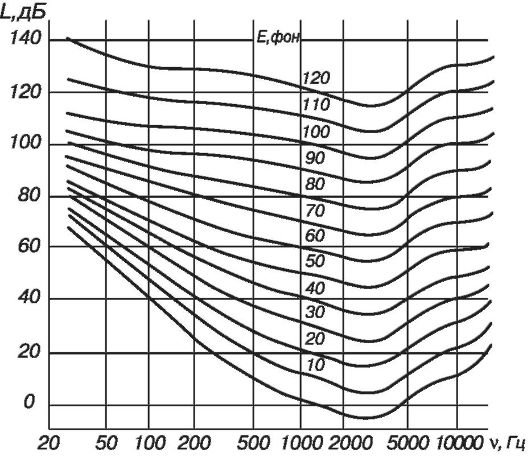 Rice. 3.3. Equal Loudness Curves
intensity L, fix the threshold level of intensity L p, at which the subject has auditory sensations. By changing the frequency of the sound, one gets experimental dependence L p (v), which is called an audiogram (Fig. 3.4).
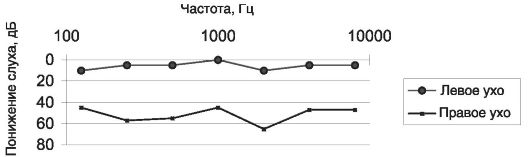 Rice. 3.4. Audiograms
Violation of the function of the sound-receiving apparatus can lead to hearing loss- a persistent decrease in sensitivity to various tones and whispered speech.
The international classification of the degrees of hearing loss, based on the average values of the perception thresholds at speech frequencies, is given in Table. 3.2.
To measure loudness complex tone or noise use special devices - sound level meters. The sound received by the microphone is converted into an electrical signal, which is passed through a filter system. The filter parameters are selected so that the sensitivity of the sound level meter at different frequencies is close to the sensitivity of the human ear.
3.4. The passage of sound through the interface
When a sound wave is incident on an interface between two media, the sound is partly reflected and partly penetrates into the second medium. The intensities of the waves reflected and transmitted through the boundary are determined by the corresponding coefficients.
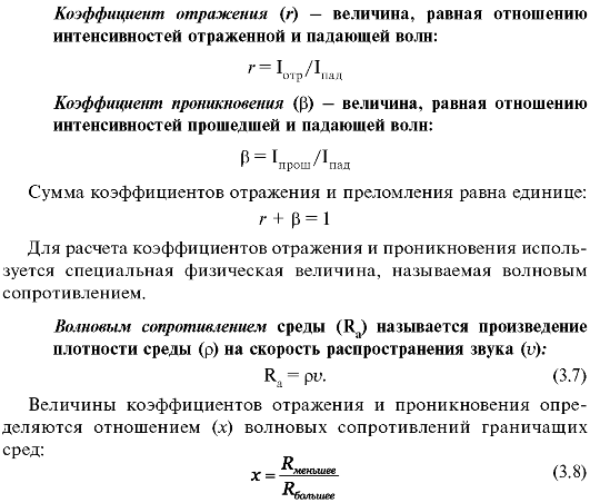 With a normal incidence of a sound wave on the interface between media, the following formulas are valid:
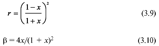 It can be seen from formula (3.9) that the more the wave impedances of the media differ, the greater the fraction of energy is reflected at the interface. In particular, if the value X is close to zero, then the reflection coefficient is close to unity. For example, for the air-water boundary X\u003d 3x10 -4, and r \u003d 99.88%. That is, the reflection is almost complete.
Table 3.3 shows the velocities and wave resistances of some media at 20 °C.
Note that the values of the reflection and refraction coefficients do not depend on the order in which the sound passes through these media. For example, for the transition of sound from air to water, the values of the coefficients are the same as for the transition in the opposite direction.
3.5. Sound research methods
Sound can be a source of information about the state of human organs.
1. Auscultation- direct listening to sounds that occur inside the body. By the nature of such sounds, it is possible to determine exactly what processes are taking place in a given area of the body, and in some cases to establish a diagnosis. Listening devices: stethoscope, phonendoscope.
The phonendoscope consists of a hollow capsule with a transmitting membrane, which is applied to the body, rubber tubes go from it to the doctor's ear. In a hollow capsule, a resonance of the air column occurs, causing an increase in sound and, consequently, an improvement in listening. Breath sounds, wheezing, heart sounds, heart murmurs are heard.
The clinic uses installations in which listening is carried out using a microphone and speaker. Wide
used to record sounds using a tape recorder on magnetic tape, which makes it possible to reproduce them.
2. Phonocardiography- graphic registration of tones and noises of the heart and their diagnostic interpretation. Recording is carried out using a phonocardiograph, which consists of a microphone, an amplifier, frequency filters, and a recording device.
3. Percussion - study of internal organs by tapping on the surface of the body and analyzing the sounds that arise during this. Tapping is carried out either with the help of special hammers, or with the help of fingers.
If sound vibrations are caused in a closed cavity, then at a certain frequency of sound, the air in the cavity will begin to resonate, amplifying the tone that corresponds to the size of the cavity and its position. Schematically, the human body can be represented by the sum of different volumes: gas-filled (lungs), liquid (internal organs), solid (bones). When hitting the surface of the body, vibrations with different frequencies occur. Some of them will go out. Others will coincide with the natural frequencies of the voids, therefore, they will be amplified and, due to resonance, will be audible. The state and topography of the organ are determined by the tone of percussion sounds.
3.6. Factors determining noise prevention.
Noise protection
To prevent noise, it is necessary to know the main factors that determine its impact on the human body: the proximity of the noise source, the intensity of the noise, the duration of exposure, the limited space in which the noise acts.
Prolonged exposure to noise causes a complex symptomatic complex of functional and organic changes in the body (and not only in the organ of hearing).
The effect of prolonged noise on the central nervous system is manifested in the slowdown of all nervous reactions, the reduction of the time of active attention, and the decrease in working capacity.
After a long exposure to noise, the rhythm of breathing, the rhythm of heart contractions changes, there is an increase in the tone of the vascular system, which leads to an increase in systolic and diastolic
cal level of blood pressure. The motor and secretory activity of the gastrointestinal tract changes, hypersecretion of individual endocrine glands is observed. There is an increase in sweating. Suppression of mental functions, especially memory, is noted.
Noise has a specific effect on the functions of the organ of hearing. The ear, like all sense organs, is able to adapt to noise. At the same time, under the influence of noise, the hearing threshold increases by 10-15 dB. After the cessation of noise exposure, the normal value of the hearing threshold is restored only after 3-5 minutes. At high level noise intensity (80-90 dB), its tiring effect increases sharply. One of the forms of dysfunction of the hearing organ associated with prolonged exposure to noise is hearing loss (Table 3.2).
Rock music has a strong impact on both the physical and psychological state of a person. Modern rock music creates noise in the ranges from 10 Hz to 80 kHz. It has been experimentally established that if the main rhythm set by percussion instruments has a frequency of 1.5 Hz and has a powerful musical accompaniment at frequencies of 15-30 Hz, then a person becomes very excited. With a rhythm with a frequency of 2 Hz, with the same accompaniment, a person falls into a state close to drug intoxication. At rock concerts, sound intensity can exceed 120 dB, although the human ear is most favorably tuned to an average intensity of 55 dB. In this case, sound contusions, sound “burns”, hearing loss and memory loss can occur.
Noise has a harmful effect on the organ of vision. Thus, prolonged exposure to industrial noise on a person in a darkened room leads to a noticeable decrease in the activity of the retina, on which the work of the optic nerve depends, and hence visual acuity.
Noise protection is quite difficult. This is due to the fact that, due to the relatively large wavelength, sound goes around obstacles (diffraction) and no sound shadow is formed (Fig. 3.5).
In addition, many materials used in construction and engineering have an insufficiently high sound absorption coefficient.
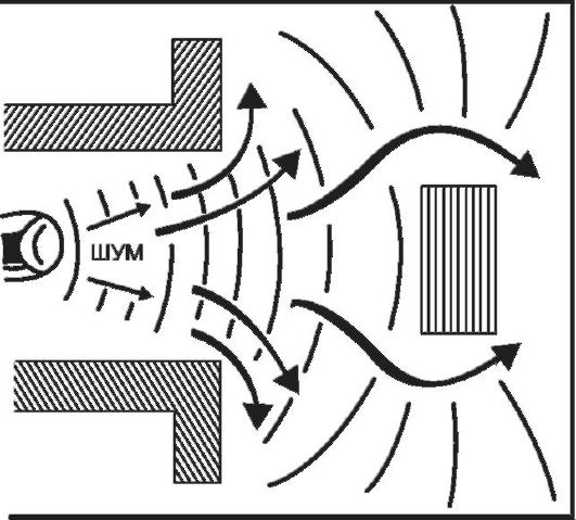 Rice. 3.5. Diffraction of sound waves
These features require special means of noise control, which include the suppression of noise that occurs in the source itself, the use of silencers, the use of elastic suspensions, soundproofing materials, the elimination of gaps, etc.
To combat noise penetrating into residential premises, proper planning of the location of buildings, taking into account the wind rose, and the creation of protective zones, including vegetation, are of great importance. Plants are a good noise dampener. Trees and shrubs can reduce the intensity level by 5-20 dB. Effective green stripes between the sidewalk and pavement. The noise is best extinguished by lindens and spruces. Houses located behind a high coniferous barrier can be spared from street noise almost completely.
The fight against noise does not imply the creation of absolute silence, since with a long absence of auditory sensations, a person may experience mental disorders. Absolute silence and prolonged increased noise are equally unnatural for a person.
3.7. Basic concepts and formulas. tables
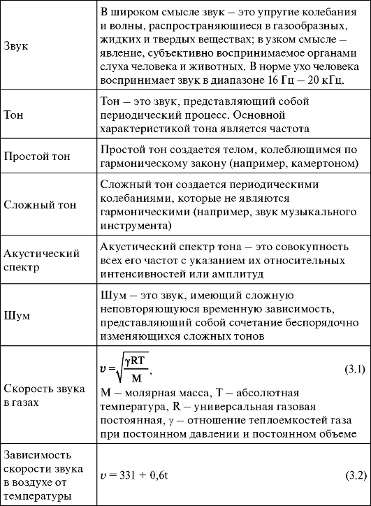 Table continuation
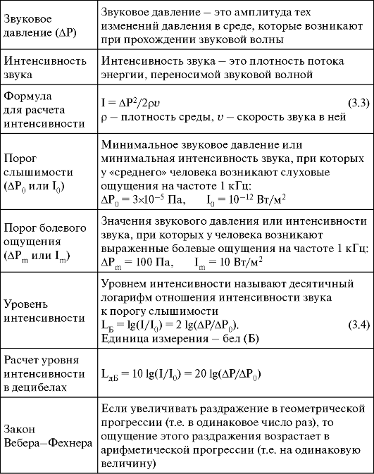 End of table
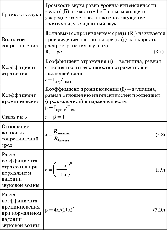 Table 3.1. Characteristics of Encountered Sounds
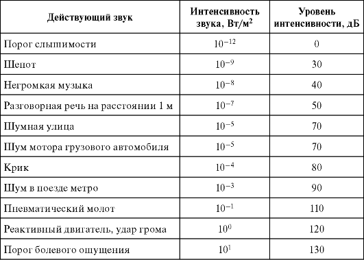 Table 3.2. International classification of hearing loss
 Table 3.3. Speed of sound and specific acoustic resistance for some substances and human tissues at t = 25 °С
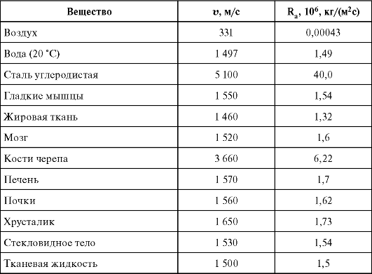 3.8. Tasks
1. The sound, which corresponds to the intensity level L 1 = 50 dB on the street, is heard in the room as the sound with the intensity level L 2 = 30 dB. Find the ratio of sound intensities in the street and in the room.
2. The volume level of sound with a frequency of 5000 Hz is equal to E = 50 phon. Find the intensity of this sound using the curves of equal loudness.
Solution
From figure 3.2 we find that at a frequency of 5000 Hz the volume E = 50 background corresponds to the intensity level L = 47 dB = 4.7 B. From formula 3.4 we find: I = 10 4.7 I 0 = 510 -8 W / m 2.
Answer: I \u003d 5? 10 -8 W / m 2.
3. The fan creates a sound whose intensity level is L = 60 dB. Find the sound intensity level when two adjacent fans are running.
Solution
L 2 = log(2x10 L) = log2 + L = 0.3 + 6B = 63 dB (see 3.6). Answer: L 2 = 63 dB.
4. The sound level of a jet aircraft at a distance of 30 m from it is 140 dB. What is the volume level at a distance of 300 m? Ignore the reflection from the ground.
Solution
The intensity decreases in proportion to the square of the distance - it decreases by a factor of 102. L 1 - L 2 \u003d 10xlg (I 1 / I 2) \u003d 10x2 \u003d 20 dB. Answer: L 2 = 120 dB.
5. The ratio of the intensities of two sound sources is: I 2 /I 1 = 2. What is the difference in the intensity levels of these sounds?
Solution
ΔL \u003d 10xlg (I 2 / I 0) - 10xlg (I 1 / I 0) \u003d 10xlg (I 2 / I 1) \u003d 10xlg2 \u003d 3 dB. Answer: 3 dB.
6. What is the intensity level of a 100 Hz sound that has the same loudness as a 3 kHz sound with intensity
Solution
Using the curves of equal loudness (Fig. 3.3), we find that 25 dB at a frequency of 3 kHz corresponds to a loudness of 30 phon. At a frequency of 100 Hz, this volume corresponds to an intensity level of 65 dB.
Answer: 65 dB.
7. The amplitude of the sound wave has tripled. a) how much has its intensity increased? b) by how many decibels did the volume increase?
Solution
The intensity is proportional to the square of the amplitude (see 3.6):
8. In the laboratory room located in the workshop, the noise intensity level reached 80 dB. In order to reduce noise, it was decided to upholster the walls of the laboratory with sound-absorbing material that reduces the intensity of sound by 1500 times. What level of noise intensity will become after that in the laboratory?
Solution
Sound intensity level in decibels: L = 10 x log(I/I 0). When the sound intensity changes, the change in the sound intensity level will be equal to:
 9.
The impedances of the two media differ by a factor of 2: R 2 = 2R 1 . What part of the energy is reflected from the interface and what part of the energy passes into the second medium?
9.
The impedances of the two media differ by a factor of 2: R 2 = 2R 1 . What part of the energy is reflected from the interface and what part of the energy passes into the second medium?
Solution
Using formulas (3.8 and 3.9) we find:
 Answer: 1/9 part of the energy is reflected, and 8/9 passes into the second medium.
First of all, let's deal with the terms, since the terms "loudspeaker", "column", "speaker", "acoustic system" are often used at random, creating a fair amount of confusion.
Speaker - this is a device designed to effectively emit sound into the surrounding space in the air, containing one or more loudspeaker heads in the presence of acoustic design and electrical devices (filters, regulators, etc.).
In domestic technical literature, an erroneous practice has developed, according to which the term "loudspeaker" (SH) is used mainly for a single loudspeaker (in foreign catalogs it is defined as loudspeaker units or loudspeaker drive element, or driver). In accordance with the requirements of GOST 16122-87, a single loudspeaker should be designated as loudspeaker head .
The term is often used for a set of Hi-Fi and Hi-End loudspeakers. acoustic system (AC) (acoustical system or loudspeaker system). Acoustic system includes acoustic speakers .
Depending on the purpose, speakers differ significantly in parameters, design and design. The main types of acoustic systems on the modern market can be conditionally divided into several categories depending on their area of application:
- Speakers for home use, which in turn can be divided into systems:
- mass;
- Hi-Fi and High-End categories;
- Speakers for home audio video complexes such as "Home Theater" (Home-Theatre);
- for modern computer systems (AC Multi-Media), etc.;
- Speakers for sound systems and sound amplification, including for conference systems and speech translation systems (these, in particular, include ceiling speakers);
- concert and theater speakers;
- studio speakers;
- automotive (and generally transport) speakers;
- Speakers for private listening (stereo headphones).
AC device
AS can be single-lane and multi-band . Single-band speakers are used, as a rule, in mass equipment of the budget sector. High-quality speakers (Fig. 1) use a multi-band construction principle, since the use of a single wide-range speaker head does not provide high sound quality.
AS usually consists of:
- loudspeaker heads, each of which (or several at the same time) operate in its own frequency range;
- corps;
- filtering and corrective circuits, as well as other electronic devices (for example, for overload protection, level indication, etc.);
- audio cables and input terminals;
- amplifiers for active acoustic systems and crossovers (active filters).
![]()
Rice. 1. Speaker system Defender
Speaker heads
Loudspeaker heads are classified according to the principle of operation, according to the method of radiation, according to the band of transmitted frequencies, according to the field of application, etc.
According to the principle of action , i.e. according to the method of converting electrical energy into acoustic, loudspeakers are divided into electrodynamic, electrostatic, piezoceramic (piezofilm), plasma, etc.
The vast majority of loudspeaker heads are electrodynamic ("dynamic" or simply "speakers"). Their principle of operation is based on the movement in a constant magnetic field of a conductor or coil powered by alternating current (Fig. 2).

Rice. 2. Electrodynamic reel-to-reel loudspeaker
The head of an electrodynamic loudspeaker consists of a moving system, a magnetic circuit and a diffuser holder (1).
The moving system includes suspension (2), diaphragm (3), centering washer (4), dust cap (5), voice coil (6) and pigtails.
When passing alternating current along the voice coil placed in the radial gap of the magnetic circuit, it will be acted upon mechanical force. Under the action of this force, axial oscillations of the coil and the diaphragm attached to it occur. The design of an electrodynamic loudspeaker is very similar to that of a dynamic microphone, so, in principle, a weak loudspeaker head can be obtained from a dynamic microphone, and a microphone can be obtained from a loudspeaker head. It is clear that all this will work disgustingly, but it will work.
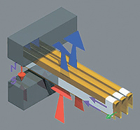
Rice. 3. Ribbon speaker
Ribbon loudspeakers (Fig. 3) use a thin metal ribbon that is placed in a magnetic field between the poles of a magnet and serves as both a current conductor and an oscillating radiating element.
Tape heads are much more efficient than dynamic, piezoelectric and others, because if the area of a conical or dome diffuser is the area of a visible circle, then the active area of a tape emitter is a full sweep of the folded membrane (the effective area is 2.5 times larger than the projection area of the folded tape). Thus, less movement of the diffuser is required to obtain the desired sound pressure level.
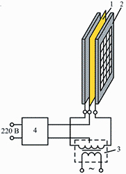
Rice. 4. Electrostatic loudspeaker
Electrostatic loudspeakers (Fig. 4) use a radiating element in the form of a thin metallized film (1) with a thickness of about 6 ... metallized movable membrane). A high polarizing voltage of the order of 8...10 kV is applied between the membrane and the electrodes. An alternating sound voltage, under the action of which the membrane vibrates and emits sound, is applied to the fixed electrodes. Loudspeakers of this type provide purity and transparency of sound due to low levels of transient distortion.
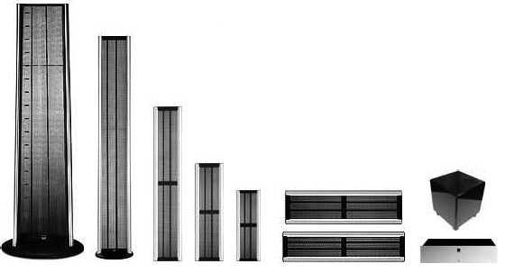
Rice. 5. Lineup of electrostatic loudspeakers Final

Rice. 6. Central loudspeaker electrostatic speaker. Model 200
On fig. 5 shows the Final range of electrostatic loudspeakers, and fig. 6 - close-up of the center speaker.
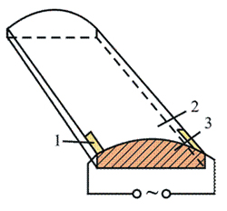
Rice. 7. Piezo-film loudspeaker
Piezoceramic (piezofilm) loudspeakers (Fig. 7) are used mainly as a high-frequency link in acoustic systems. As an exciting element, they use a bimorph element obtained by connecting two plates (1), (3) of piezoceramics (titanium zirconate, barium titanate, etc.). The bimorph element is fixed on both sides; when an electrical signal is applied, bending deformations occur in it, which are transmitted to the diaphragm (2) connected to it. A variation of this type of loudspeakers are piezo-film radiators, they use high-polymer films, which, using a specially developed technology, are given piezoelectric properties (when they are polarized in a strong magnetic field). If such a film is given the shape of a dome or cylinder, then under the action of an alternating voltage applied to it, it begins to vibrate and emit sound; such loudspeakers do not require the use of a magnetic circuit.
According to the method of emitting acoustic energy, the loudspeaker heads are divided into direct-radiation heads, in which the diaphragm emits sound directly into environment, and horn (Fig. 8), in which the diaphragm emits sound through the horn. If a horn has a pre-horn chamber, then it is called a narrow-mouth horn, and if only a horn is used, then it is a wide-mouth horn.
Rice. 8. Horn loudspeaker
Horn loudspeakers are widely used in the creation of sound systems for streets, stadiums, squares, sound amplification systems in various rooms, high-quality household systems, warning systems, etc.
The reasons for the spread of horn loudspeakers are primarily due to the fact that they are more efficient, their efficiency is 10-20% or more (in conventional loudspeakers, the efficiency is less than 1...2%); in addition, the use of rigid horns makes it possible to form a given directivity characteristic, which is very important when designing sound amplification systems. However, when using horn loudspeakers, there are problems associated with the fact that in order to emit low frequencies, it is necessary to significantly increase the size of the horn, and high sound pressure levels in the pre-horn chamber create additional non-linear distortions.
The design of the loudspeaker heads depends on the frequency band in which they must operate. On this basis, speakers are divided into:
- broadband (OO "full-range");
- low-frequency (reproducible range of approximately 20-40 ... 500-1000 Hz) ("woofer", "subwoofer");
- mid-frequency (range 0.3-0.5 ... 5-8 kHz) ("mid-range");
- high-frequency (1-2..16-30 kHz) (“tweeter”), etc.
Most of the power of audio signals is usually low frequency GG, therefore, they must perceive loads up to 200 W or more, while maintaining thermal and mechanical strength. These GGs have a low resonant frequency (16...30 Hz) and must be designed for a large stroke of the moving system up to ±12...15 mm.
The appearance of a modern low-frequency GG for high-quality speakers is shown in fig. 9.
The main radiating element of a loudspeaker is the diaphragm. Diaphragms of modern low-frequency GGs are made from complex compositions based on natural long-fiber cellulose with various additives. Sometimes the composition of such a composition includes up to 10-15 components. Synthetic film compositions based on polyolefins (polypropylene and polyethylene) and composite materials based on Kevlar fabric are increasingly being used.

Rice. 9. Woofer
Home theater speakers (especially center and front channels, as well as a subwoofer) require the use of carefully shielded low frequencies.
Mid range loudspeakers (MF GG) are used in the frequency range from 200...800 Hz to 5...8 kHz, where hearing sensitivity to all types of distortion is maximum, so the requirements for their quality are the most stringent.
Tweeters (HF GG). (Fig. 10). Requirements for them last years increased sharply due to the increase in the spectral power density in the high-frequency part of the spectrum in modern electronic music, the expansion of the frequency and dynamic range of programs reproduced by digital sound reproducing equipment, etc.
In modern speakers, high-frequency GGs are used, as a rule, in the frequency range from 2 ... 5 to 30 ... 40 kHz. It is extremely difficult to provide equivalent high-quality sound reproduction in such a wide range using one GG. Therefore, most of the HF GGs currently produced are used in the range from 2 ... 5 to 16 ... 18 kHz, and in some speakers additional small-sized HF GGs are installed (reproducing frequencies from 8 ... 10 to 30 ... 40 kHz).
![]()
Rice. 10. HF GG
Ceiling speakers
Ceiling loudspeakers are typically electrodynamic cone loudspeakers enclosed in plastic or metal enclosures. They are used for scoring rooms and in emergency warning systems of buildings. Due to the large opening angle of the sound pattern and the wide range of reproducible frequencies, the ceiling speakers are capable of reproducing sound quite well, in addition, they harmoniously fit into almost any interior.
Ceiling loudspeakers provide a more even distribution of sound throughout the room compared to other loudspeakers and do not require the installation of powerful amplifiers. Their use is especially effective for scoring large rooms with a ceiling height of up to 5 m.
For ease of installation, the ceiling loudspeaker housing is equipped with special devices: spring-loaded stops, skids or brackets. Many loudspeakers are attached to ceiling tiles with screws. Unlike "conventional" PA systems, ceiling speaker systems are high voltage, typically 100V line voltage, so ceiling speakers have built-in transformers.
When designing a public address system, the calculation of the required number of ceiling loudspeakers and their placement (Fig. 11) is based on the required sound pressure level at the level of the listeners' ears (usually an average value of 1.5 m is taken). For rooms with a ceiling height of less than 5 meters, such a calculation is not difficult and is carried out according to approximate formulas. Table 1 shows the number of ceiling speakers for a given ceiling height and room area that gives the best sound quality and the most even distribution of sound waves.
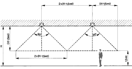
Rice. 11. Ceiling speaker layout
The S parameter in the table is the approximate area covered by one ceiling loudspeaker:
S \u003d (2x (H - 1.5 m)) 2, where H is the height of the ceiling.
Table 1. To the calculation of the warning system
| P | 103,5 | 101 | 99 | 97,5 | 96 |
| P/2 | 100,5 | 98 | 96 | 94,5 | 93 |
| H/S | 3 | 3,5 | 4 | 4,5 | 5 |
| 25 | 2 | 1 | 1 | 1 | 1 |
| 35 | 3 | 2 | 1 | 1 | 1 |
| 50 | 4 | 2 | 1 | 1 | 1 |
| 80 | 6 | 3 | 2 | 2 | 1 |
| 100 | 7 | 4 | 3 | 2 | 2 |
| 150 | 10 | 6 | 4 | 3 | 2 |
| 200 | 13 | 8 | 5 | 4 | 3 |
| 300 | 20 | 11 | 7 | 5 | 4 |
| 400 | 26 | 15 | 10 | 7 | 5 |
| 500 | 33 | 19 | 12 | 8 | 6 |
| 600 | 40 | 22 | 14 | 10 | 8 |
| 700 | 46 | 26 | 17 | 12 | 9 |
| 800 | 53 | 30 | 19 | 13 | 10 |
| 900 | 59 | 33 | 22 | 15 | 11 |
| 1000 | 66 | 37 | 24 | 17 | 12 |
In the table:
P is the sound pressure at 1.5 m when the ceiling loudspeaker is operating at full power;
P/2 is the sound pressure at 1.5 m when the ceiling loudspeaker is operating at half maximum power;
H - ceiling height;
S is the area of the room.
Ceiling speakers are not recommended for ceiling heights greater than 5 meters. However, if ceiling speakers are to be used, care must be taken to improve sound distribution and reduce reverberation (echo). If the ceiling speakers are placed too close together, the sound will be distributed unevenly at the level of the listeners' ears. If you increase the distance between adjacent speakers, the sound pressure level may not be sufficient for good audibility. Increasing the sound level of the loudspeakers in this case entails an increase in reverberation, especially in rooms decorated with glass, marble, etc. Reverberation can be reduced by using sound-absorbing materials such as carpets, tapestries, curtains, etc.
On fig. Figures 12 and 13 show examples of Kramer Electronics in-ceiling and in-ceiling loudspeakers.
Speaker box. The main types of buildings and their purpose
The speaker cabinet performs a variety of functions. In the bass region, it blocks the effect of "acoustic short circuit", which occurs due to the addition of the emitted sound from the front and rear surfaces of the diaphragm in antiphase, which leads to the suppression of low-frequency radiation.
The use of the housing allows to increase the radiation intensity at low frequencies, as well as to increase the mechanical damping of the loudspeakers, which makes it possible to “smooth out” resonances and reduce the unevenness of the amplitude-frequency characteristic. The cabinet has a significant impact not only in the low, but also in the medium and high frequencies. A properly designed and manufactured cabinet has a huge impact on sound quality.
When designing speaker cabinets, such design options are most often used as an endless screen, a closed cabinet, a bass-reflex cabinet, a labyrinth, a transmission line, etc.
Infinite Screen occurs when loudspeakers are installed in the wall of a room with a sufficiently large volume behind it. This loudspeaker setup tends to have a “thumbling” effect at low frequencies because there is no damping.
Closed body. In modern speakers, mostly closed compression-type cases are used. The principle of operation of the compression design is that they use loudspeakers with a very flexible suspension and a large mass, i.e. low resonant frequency. In this case, the elasticity of the air in the body becomes the determining factor, it is she who begins to make the main contribution to the restoring force applied to the diaphragm.
Chassis with phase inverter- a housing in which a hole is made, which allows the use of radiation from the rear surface of the diffuser. The maximum effect is achieved in the resonance frequency region of the oscillatory system, which is formed by the mass of air in the hole or pipe and the mass of air in the housing.
Casings with a phase inverter (Fig. 14 a) have many varieties. The case, using a special pipe inserted into the hole, allows you to reduce the size of the case and adjust the phase inverter by adjusting the size of the pipe (Fig. 14 b).
If a passive (i.e., without a magnetic circuit) loudspeaker is installed in the opening of the housing, the oscillations of which are excited by fluctuations in the volume of air enclosed in the housing, then such a housing is called a housing with a passive radiator (Fig. 14 c).
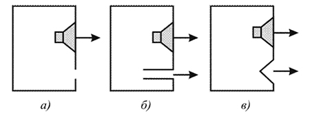
Rice. 14. Speaker cabinet with various options for phase inverters: a - phase inverter; b - phase inverter with a pipe; c - passive radiator
labyrinth is a variant of the case with a phase inverter, in which special partitions are installed. When the length of the labyrinth reaches 1/4 wavelength at the resonance frequency of the subwoofer, it acts like a phase inverter. The use of a labyrinth expands the possibilities for tuning to lower frequencies. Resonances at harmonics from the main resonant frequency of the pipe are damped by sound-absorbing materials on the walls of the case (Fig. 15 a).

Rice. 15. The case of the speaker type of labyrinth (a) and the type of transmission line (b)
transmission line It's a kind of labyrinth. It differs from the labyrinth in that the entire volume of the body is clogged with sound-absorbing material, and the cross section of the line is made variable - more at the cone, less at the hole (Fig. 15 b). Cases of this type are very difficult to set up.
If two identical GGs are installed in the case on one phase inverter, then this is called "low-frequency design with a symmetrical load." This design is often used in subwoofers.
Speakers with smoothed corners, streamlined shape, with an asymmetrical arrangement of the GG sound better, however, it is difficult and expensive to manufacture cases of such speakers, so the vast majority of speakers are produced in rectangular cases. To reduce diffraction effects at the corners of the front panel, special measures are taken, including the placement of sound-absorbing materials (“acoustic blanket”), optimization of the ratio of front panel dimensions and case depth, selection of an asymmetrical arrangement of loudspeakers, etc.
The desire to shift the diffraction peaks-dips in the frequency response to a higher frequency region and thereby reduce their influence forces the use of the most narrow front panels. The complex exterior configurations of many modern loudspeakers are driven not only by aesthetic considerations, but also by the desire to reduce diffraction effects. In order to reduce the sound radiation from the walls of the speakers, they usually try to increase their rigidity and mass.
In modern speakers, the case is a rather complex and expensive structure (Fig. 16). As a criterion for the effectiveness of the measures taken to soundproof the cabinet, it is customary to consider the difference between the sound pressure level emitted by the cabinet walls and the sound pressure level from the speaker system as a whole, it should be at least 20 dB.
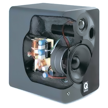
Rice. 16. Section AC
In addition to objective measurements, when designing, listening to speakers in cases of various designs is carried out.
Filtering and correcting circuits
It is almost impossible or difficult to provide high-quality sound reproduction using single-way speakers, so they are used only in budget solutions, for example, in cheap speakers for computers. High-quality speakers, with rare exceptions, are multi-band. In order to apply signals of its own frequency subrange to each GG, electrical separation filters (“crossovers”) are used.
Most speakers for home use use the so-called. passive filters, which are included between the amplifier and the loudspeaker (Fig. 17).
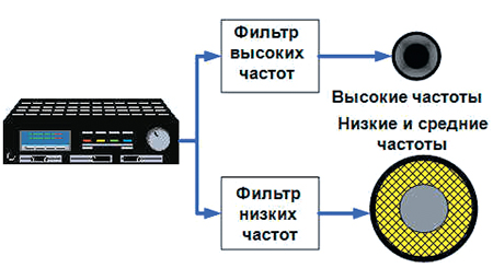
Rice. 17. Passive filters ("passive crossovers") in speakers
Passive filters are usually placed inside speakers, increasing their weight and dimensions. Passive filters in speakers are of the first, second, third and fourth order. The slope of the first order filters is 6dB/octave, the second is 12dB/octave, the third is 18dB/octave and the fourth is 24dB/octave.
The simplest filters are first-order filters, they take up little space and are inexpensive, but have insufficient passband rolloff. A positive feature of these filters is the absence of a phase shift between the tweeter (HF head) and the other speaker.
Second-order filters (or Butterworth filters, after the name of the creator mathematical model these filters) have a higher sensitivity, but give a phase shift of 180 degrees, which means that the membranes of the tweeter and other speaker are not synchronized. To fix this problem, you need to reverse the polarity of the wires on the tweeter.
Third order filters have good phase characteristics with any connection polarity. On fig. 18 shows the frequency response of the filter of the third order, and in fig. 19 - its electrical circuit.
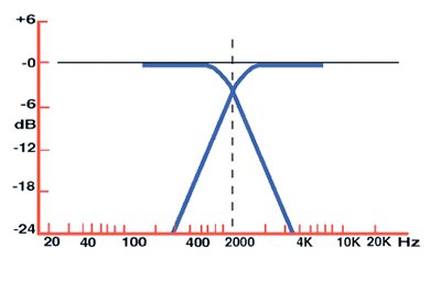
Rice. 18. Frequency response of the third order filter
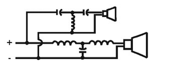
Rice. 19. Electrical circuit of the filter of the third order

Rice. 20. Frequency response of a three-band filter
In three-band AC, the frequency response of the filter looks like that shown in Fig. twenty.
Fourth-order Butterworth filters have high passband roll-off, which dramatically reduces speaker interference in the crossover region. The phase shift is 360 degrees, that is, in practice it is absent. However, the problem is that such filters have a variable phase shift, which can cause unstable operation of the speaker. Linkwitz and Riley succeeded in optimizing the fourth-order filter scheme for AS. Their filter consists of two series-connected second-order Butterworth filters for high-frequency HG and for low-frequency GG. Such a filter has no phase shifts and allows time correction for speakers that do not radiate sound in the same plane. These filters provide the very best acoustic performance.
In "active" speakers with built-in multiband amplifiers, active filters are used, connected before the amplifier and also called crossovers (Fig. 21).

Rice. 21. Using crossovers
Compared to passive filters, active filters have a number of advantages: smaller dimensions, better crossover frequency tunability, greater stability of characteristics, etc. However, passive filters provide a greater dynamic range, less noise and non-linear distortion. Their disadvantages include temperature instability, which leads to a change in the shape of the frequency response with an increase in the level of the input signal (the so-called "power compression"), as well as the need for careful selection of high-precision elements (resistors, capacitors, etc.), to the spread of parameters which the filter characteristics can be very sensitive. In recent years, a number of foreign firms have begun to use digital filters in acoustic systems, which provide real-time filtering, correction, and adaptation to real listening conditions.
In addition to filters, modern acoustic systems often use electronic devices to protect loudspeakers from thermal and mechanical overloads. Protection from both long-term and short-term (peak) overloads is carried out using various options for threshold circuits, the response thresholds of which should be less than the thermal constants of the loudspeaker heads (T = 10 ... 20 ms). In addition, many household systems use various options for indicating overloads.
Main characteristics of speakers
There are quite a few characteristics of the AU, some of them are of greater importance to the user, others are less important, domestic and foreign characteristics of the AU and methods for measuring them do not always coincide. We will briefly review only the main characteristics of the speakers.
Efficient worker (effectively reproducible) frequency range - the range within which the sound pressure level developed by the AU is not lower than the specified one, in relation to the level averaged over a certain frequency band. In IEC 581-7 recommendations minimum requirements to this parameter are 50 - 12500 Hz with a decline of 8 dB in relation to the level averaged over the frequency band 100 - 8000 Hz.
The value of this characteristic greatly affects the natural sound of acoustics. The closer the operating range of the speakers is to the maximum range perceived by the human hearing organs (16 - 20,000 Hz), the better, more natural the speaker sounds. The effective operating range depends on the characteristics of the loudspeaker heads, on the acoustic design of the speakers and on the parameters of the crossover filter (crossover).
At low frequencies, the volume of the speaker cabinet plays a decisive role. The larger it is, the more effectively low frequencies are reproduced, so, in particular, subwoofers are always quite bulky. With the reproduction of high frequencies, problems usually do not arise, since modern tweeters allow even ultrasound to be reproduced. Often the range of reproducible frequencies of the speakers exceeds the upper limit of human hearing. It is believed that in this case the timbre of a complex phonogram, for example, symphonic music, is more accurately transmitted. Typical values: 100 - 18000 Hz for bookshelf speakers and 60 - 20000 Hz for floorstanders.
Serious loudspeaker manufacturers usually give a graph of the sound pressure developed by the loudspeaker as a function of frequency (an amplitude-frequency characteristic (AFC) graph), by which one can determine the effective operating frequency range of the loudspeaker and the unevenness of the frequency response.
The degree of frequency response unevenness is characterized by the ratio of the maximum value of the sound pressure to the minimum, or by another method, the ratio of the maximum (minimum) value to the average, in a given frequency range, expressed in decibels. The IEC 581-7 recommendation, which defines the minimum requirements for Hi-Fi equipment, states that the frequency response flatness should not exceed ± 4 dB in the range of 100 - 8000 Hz.
Directivity allows you to evaluate the spatial distribution of sound vibrations emitted by the acoustic system, and optimally position the acoustic systems in different rooms. This parameter allows you to judge the directional diagram of the speaker, which is the dependence of the sound pressure level on the angle of rotation of the speaker relative to its working axis in polar coordinates, measured at one or more fixed frequencies. Sometimes the decrease in the amplitude-frequency response when the speaker is rotated by some fixed angle is displayed on the main graph, in the form of additional frequency response branches.
Characteristic sensitivity - this is the ratio of the average sound pressure developed by the AU in a given frequency range (usually 100 - 8000 Hz) on the working axis, reduced to a distance of 1 m and the input electrical power 1 W. Most Hi-Fi speakers have an intrinsic sensitivity level of 86-90 dB (dB/m/W is often used in technical literature instead of dB). There are high-quality broadband speakers with a sensitivity of 93 - 95 dB / m / W or more.
Intrinsic sensitivity determines how much dynamic range a speaker can provide. A wide dynamic range allows you to reproduce complex musical works, especially jazz, symphonic, chamber music, with great reliability.
THD characterizes the appearance in the process of conversion of spectral components that were absent in the original signal, distorting its structure, that is, ultimately, the fidelity of reproduction. This is a very important parameter, since the contribution of speakers to the total coefficient of non-linear distortion of the entire audio path, as a rule, is the maximum. For example, the coefficient of non-linear distortion of a modern amplifier is hundredths of a percent, while the typical value of this parameter for speakers is a few percent. As the signal power increases, the non-linear distortion factor increases.
Electrical (acoustic) power – determines the sound pressure level and dynamic range (taking into account the characteristic sensitivity) that the speakers can potentially provide in a particular room.
Several types of capacities defined by different standards are used:
Characteristic power , at which the speaker provides a given level of average sound pressure. The IEC recommendations set this level to 94 dB at a distance of 1 meter.
Maximum (limiting) noise or nameplate power at which the speaker can work for a long time without mechanical and thermal damage when tested with a special noise signal that is close in spectrum to real music programs (pink noise). According to the measurement technique, it coincides with the nameplate power, determined in domestic standards.
Maximum (limiting) sinusoidal power - the power of a continuous sinusoidal signal in a given frequency range, at which the speaker can operate for a long time without mechanical and thermal damage.
Maximum (limiting) long-term power that acoustics can withstand without mechanical and thermal damage for one minute, with the same test signal as for nameplate power. The tests are repeated 10 times with an interval of 1 minute.
Maximum (limiting) short-term the power that the AU can withstand when tested with a noise signal with the same distribution as for nameplate power, for 1 second. The tests are repeated 60 times with an interval of 1 minute.
Peak (maximum) musical power - a favorite parameter for characterizing speakers of unknown origin. The measurement technique, defined by the German standard DIN 45500, is as follows: a signal with a frequency below 250 Hz and a duration of less than 2 seconds is applied to the speakers. Acoustics is considered to have passed the test if there are no noticeable distortions. It is clear that “under the distortions noticeable by ear” you can understand anything. As a result, stickers like “P.M.P.O. … (or Musical Power…)…100!, …200! and even… …1000 Wt!”. It is clear that there is no need to talk about at least some quality sound created by such speakers.
When choosing speakers for ULF, it is desirable that the actual maximum speaker power exceed the amplifier power by approximately 30 percent or more. In this case, you will be insured against the failure of the acoustics due to the supply of an unacceptably high level signal to it. Of course, good speakers have overload protection circuits, but it's better not to risk it.
What amplifier power is sufficient for high-quality sound reproduction? This is largely determined by the parameters of the room, the characteristics of the acoustic systems, the needs of the listener himself. When choosing an amplifier for sounding a small living room, we can assume that the power of the amplifier should be at least 20 watts.
Most Common Values electrical (input) resistance (impedance): 4, 8 or 16 ohms. This parameter is important when choosing an amplifier with which the speakers will work. You should use speakers with an impedance corresponding to that specified in the amplifier's passport. Such a solution will provide an ideal match between the characteristics of the acoustics and the amplifier, that is, the best sound quality.
Measurement of the characteristics of the speakers in conditions that differ from the conditions of specially equipped acoustic laboratories of manufacturers is an extremely complex, costly and, most importantly, giving very approximate results. High-quality sound analyzers and measuring microphones with preamplifiers that meet all international measurement requirements are extremely expensive and not every Russian company can afford to purchase them. True, modern measurement techniques in most cases will make it possible to do without an acoustically dampened chamber.
Audio cables
Audio cables are, at first glance, the least important component of the audio subsystem of an installation or home theater, so they are often purchased, what is called "in change". And they make a big mistake.
It is clear that any cable affects the signal passing through it. The question is how exactly the cable affects the signal and how much this influence is.
The choice of audio cables is determined by the quality parameters of the audio signal on the one hand and constructive and financial considerations on the other. Indeed, some installations require hundreds of meters of audio cables to be laid. You can calculate how much it will cost, for example, silver microphone cables with a total weight of 100 kg ...
Conductors in any electrical cable or wire are metals. Audio cables use mostly copper and silver. In 1984, Hitachi released the SAX-102 interconnect cable, which immediately attracted the attention of professionals. It was made from the so-called oxygen-free copper OFC (Oxygen Free Copper). Now almost all specialized "cable" firms use such copper. Why is oxygen-free copper good? The conductor metal can be viewed as a series connection of metal granules. Inside each granule crystal structure retains its ideality, but the interfaces between the granules violate the crystal lattice. As a rule, the causes of the appearance of interfaces are films of oxides, oxygen compounds with metals. Due to the fact that OFC is cast and stretched in a certain way, the length of the ideal pellets is increased. Typical high purity copper contains about 5,000 grains per meter of cable. Improvement in OFC technology has led to the emergence of higher quality OFHC (Oxygen Free High Conductivity) oxygen-free high-conductivity copper, the number of grains per meter of which was 1000. There are other varieties of oxygen-free copper wire technology.
Similar technologies are applied to silver conductors. The result is highly refined, long grained silver such as AudioQuest's FPS (Functionally Superior Silver) or PSS (Perfect Surface Silver). These are very expensive wires. Silver is often used as a cladding coating on copper wire, and the surface is polished to a mirror finish to eliminate the potential effect of inhomogeneities on signal transmission.
As insulators for audio wires and cables in household appliances, mainly polyethylene, polyvinyl chloride and fluoroplastic (known as Teflon) are used. For external coatings of cables, artificial rubbers, silicone rubbers, polypropylenes, etc. are used. Polyethylene is most often used, fluoroplast has the best dielectric characteristics, but it is relatively expensive, which hinders its use. Sometimes foamed polyethylene or fluoroplast is used as an insulator.
Since audio cables connect the amplifier to the speakers and operate with rather high currents, designers first of all pay attention to active resistance conductor: the smaller it is, the better. Firstly, because the ohmic resistance of the cable is connected in series with the ULF output resistance and the AC input resistance, and a relatively high-resistance connecting wire can drastically degrade the quality of the ULF and AC, and, secondly, according to the Joule-Lenz law, the thermal heating of the wire is proportional to the second the degree of current flowing through it. Reducing the ohmic resistance of the conductive lines is achieved by increasing their cross section. Therefore, the audio cables are quite thick. Acoustic wires are relatively low-frequency (the operating range is 4-5 orders of magnitude: from units of hertz to hundreds of kilohertz). And yet, most developers, having achieved the minimum value resistivity(0.001–0.05 Ohm/m), try to reduce the inductance of the wire (a typical value of specific inductance is 0.2–0.5 μH/m). Almost all wires, with the exception of flat tape ones, are made in the form of bundles assembled from separate thin wires. The simplest are a pair of insulated conductors ("noodles"); this design is most common due to its lowest cost. Twisted veins constantly change their position: some go inward from the surface, others, on the contrary, go from the center to the surface. Since the distribution of current density over the cross section of the conductor does not change in order to remain close to the surface of the cable, the current passes through the interface from one strand to another. It happens that the contact between individual strands is not always good (there is a layer of oxides on the surface of each strand that conducts current poorly), and numerous transitions through resistance barriers can theoretically affect the transmitted signal. If you cut the old network wire in rubber insulation, a dark film of oxides attracts attention. Such a wire is not soldered without stripping, the ohmmeter shows a rather large resistance ...
To reduce the influence of the skin effect, each thin core is sometimes provided with its own insulation, however, such cables are not technologically advanced, since it is difficult to automate the process of cutting the cores of such a cable.
Speaker cables are characterized by a wide variety of designs that differ not only in internal structure, but also in external features: round in cross section, flat, like thin ribbons, single, double, quadruple, etc. In spite of high cost, flat wires are very popular in home theater installations as they are easily hidden under wallpaper, carpets, etc. Twin wires in pairs are in demand, which are convenient for connecting acoustics according to Bi-Wiring and Bi-Amping schemes.
A variety of speakers are home theater speakers, which have specific requirements. These will be discussed in a separate brochure.


 Английский вокруг нас исследовательская работа")
