Basic formulas in dynamics according to theoretical mechanics. Forces of inertia of a rigid body. General theorems of dynamics
Lecture notes on the subject
THEORETICAL MECHANICS
For students of the specialty:
260501.65 Food service technology,
Full-time form of education
The lecture notes are based on:
1. Butorin L.V., Busygina E.B. Theoretical mechanics. Educational and practical guide. - M., MGU TU, 2004
2. Targ S.M. Short course theoretical mechanics. – M.: graduate School, 2001 - With.
3. Yablonsky A.A., Nikiforova V.N. Course of theoretical mechanics. M. "Lan", 2000
Introduction
Modern industrial production, including food, are highly mechanized industries. The solution of more and more complex tasks is assigned to technological equipment, which in turn leads to the complication of equipment. The formation of a modern engineer is unthinkable without knowledge of fundamental disciplines. One of these disciplines is theoretical mechanics .
Theoretical mechanics is a branch of mechanics that sets out the basic laws of mechanical motion and mechanical interaction of material bodies. Mechanical movement is called the change over time of the relative position in space of material bodies, mechanical interaction- such an interaction, as a result of which the mechanical movement changes or the relative position of body parts changes.
Theoretical mechanics is usually divided into: statics, kinematics and dynamics .
In statics, conditions are studied equilibrium material bodies and methods of identical transformation of the system of forces. Equilibrium A state in which a body remains stationary or moves uniformly in a straight line under the action of forces.
In kinematics, the general geometric characteristics of the motion of bodies are considered. The forces acting on the body are not considered. The law of motion is given. Law of motion of the body is the dependence of the position of the body in space on time.
In dynamics, the general laws of motion of bodies under the action of forces are studied.
1. C tatika solid body
1.1 Basic concepts of statics
Absolutely rigid body (rigid body, body)- a material body, the distance between any points in which does not change. Consequence the size and shape of the body do not change.
Material point is a body whose dimensions, according to the conditions of the problem, can be neglected.
loose body- a body, on the movement of which no restrictions are imposed.
Non-free (bound) body– a body whose movement is restricted.
Connections- bodies that prevent the movement of the object under consideration (a body or a system of bodies).
mechanical system- a set of interconnected bodies or material points.
A rigid body can be considered as a mechanical system whose positions and distances between points do not change.
Strength- a vector quantity characterizing the mechanical action of one material body on another.
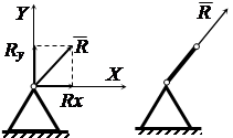
Force as a vector is characterized by the point of application, the direction of action and the absolute value (Fig. 1.1). The unit of measure for the modulus of force is Newton.
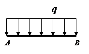 |
Fig.1.1. Fig.1.2.
line of force is the straight line along which the force vector is directed.
Concentrated Power is the force applied at one point.
Distributed forces (distributed load)- forces acting on all points of the volume, surface or length of the body (Fig. 1.2).
The distributed load is set by the force acting per unit volume (surface, length). The dimension of the distributed load is N / m 3 (N / m 2, N / m).
External force is a force acting from a body that does not belong to the considered mechanical system.
inner strength- force acting on material point mechanical system from the side of another material point belonging to the system under consideration.
Force system- a set of forces acting on a mechanical system.
Flat system of forces- a system of forces whose lines of action lie in the same plane.
Spatial system of forces- a system of forces whose lines of action do not lie in the same plane.
Converging force system- a system of forces whose lines of action intersect at one point (Fig. 1.3).
Arbitrary system of forces- a system of forces whose lines of action do not intersect at one point. (Fig. 1.4)
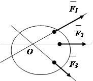 |
Fig.1.3 Fig.1.4
Equivalent systems of forces- such systems of forces, the replacement of which one for another does not change the mechanical state of the body. Accepted notation:
Balanced system of forces- a system of forces that, when applied to a free solid body, does not change its mechanical state (does not unbalance it).
![]()
resultant force- a force whose action on a body is equivalent to the action of a system of forces.
![]()
Moment of power- a value characterizing the rotational ability of the force.
Power couple- a system of two parallel, equal in absolute value, oppositely directed forces. The accepted designation is (). Under the action of a pair of forces, the body will perform rotational motion.
Projection of Force on the Axis- a segment enclosed between perpendiculars drawn from the beginning and end of the force vector to this axis (Fig. 1.5).
The projection is positive if the direction of the segment coincides with the positive direction of the axis.
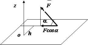
Projection of Force on a Plane- a vector on a plane enclosed between perpendiculars drawn from the beginning and end of the force vector to this plane (Fig. 1.6).

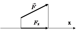
Fig.1.5 Fig.1.6
1.2. Axioms of statics
The theoretical principles of statics are based on a number of axioms. An axiom is a law formulated as a result of generalizing the results of observations.
1. Axiom of balance.
Two forces acting on a rigid body are balanced only if they are equal in absolute value and act along one straight line in opposite directions (Fig. 1.7).
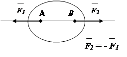
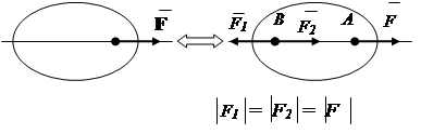
Fig.1.7 Fig.1.8
2. Axiom of addition (exclusion) of a balanced system of forces.
The action of a system of forces on a rigid body will not change if a balanced system of forces is added to or excluded from it (Fig. 1.8).
3. Axiom about the parallelogram of forces.
A system of two forces applied at one point of a rigid body has a resultant force applied at the same point. The resultant vector is the diagonal of the parallelogram built on these forces (Fig. 1.9).
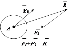
Rice. 1.9 Fig.1.10
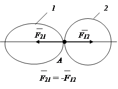
4. Axiom of counteraction.
When one solid body acts on another, a reaction force arises, equal in absolute value, opposite to the acting force (Fig. 1.10).
Note. The force whose action is given is called active force, the reaction force is called reaction .
5. Axiom of connections.
Any non-free body can be considered as free, if it is mentally freed from bonds, replacing their action with the corresponding reactions.
1.3 Bonds and their reactions
The bodies that prevent the movement of the object under consideration will be called constraints. The force with which the bond acts on the object in question is called bond reaction. When determining possible coupling reactions, one should proceed from the fact that the reaction is a force that prevents the movement of the body in question. The reaction is directed in the opposite direction to where the connection does not allow the body to move.
Let's look at some common connections.
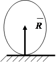
Smooth surface restricts movement along the normal to the support surface. The reaction is directed perpendicular to the surface (Fig. 1.11).
Articulated movable support limits the movement of the body along the normal to the reference plane. The reaction is directed along the normal to the support surface (Fig. 1.12)
Articulated fixed support counteracts any movement in a plane perpendicular to the axis of rotation. In calculations, the reaction Fr, as a rule, is presented as two components along the X and Y axes (Fig. 1.13).
Articulated weightless rod counteracts the movement of the body along the line of the rod. The reaction will be directed along the line of the rod (Fig. 1.14).
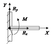
Blind termination counteracts any movement and rotation in the plane (Fig. 1.15). Its action can be replaced by a force presented in the form of two components and a pair of forces with a moment.
 |
 |
 |
|
Fig.1.11 1.12 Fig.1.13 Fig.1.14 Fig.1.15
1.4 Moment about a point
Under the action of a force, a rigid body, along with translational motion, can rotate around a particular center. The rotational ability of a force is characterized by a moment of force. The rotational effect of the force depends on the modulus of the force, the distance from the center to the line of action of the force, and the direction of rotation in the plane of rotation.
The absolute value of the moment is equal to the product of the modulus of force and the shortest distance h from the center of rotation to the line of action of the force. Distance h called shoulder of strength (Fig. 1.16).
M 0 () = F× h , (1.1)
The moment is considered positive if the force tends to rotate the arm h counterclockwise and negative when rotating clockwise.
Properties of the moment of force about a point:
1. The moment of force will not change when the point of application of force is moved along the line of action of the force.
2. The moment of force is equal to zero if the line of action of the force passes through the point of application of the force.
3. Moment of the resultant force about a point is equal to the sum moments of the terms of forces about this point.
 |
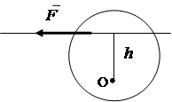 |
Fig.1.16. Fig.1.17.
1.5. Moment of force about the axis
The moment of force about an axis is the moment of projection of this force onto a plane perpendicular to the axis, relative to the point of intersection of the axis with the plane.
The moment is considered positive if, from the positive end of the axis, the rotation that the force seeks to make is seen as occurring counterclockwise, and negative if it is clockwise.
![]() . (1.3)
. (1.3)
To find the moment of force about the axis, you need (Figure 1.17);
1. Draw a plane perpendicular to the z-axis.
2. Project the force onto this plane and calculate the projection value .
3. Hold your shoulder h from the point of intersection of the axis with the plane to the line of action of the force projection and calculate its length.
4. Find the product of this shoulder and the force projection with the corresponding sign /
Properties of the moment of force about the axis
The moment of force about the axis is zero if:
1. , i.e. force is parallel to the axis.
2. h =0 , i.e. the line of action of the force intersects the axis.
1.6. Moment of a pair of forces
A pair of forces exerts a rotating effect on the body. The moment of a pair of forces is equal to the product of one force by the shortest distance between the lines of action of the forces of the pair, which is called the shoulder of the pair (Fig. 1.18)
![]() , (1.4)
, (1.4)
where: - the forces that make up the pair;
h- couple's shoulder
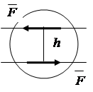 |
Fig.1.18.
The moment of the couple is considered positive if the forces tend to rotate the arm counterclockwise.
Force couple properties
1. The sum of the projections of the forces of a pair on any axis is zero.
2. Without changing the moment of the pair, you can simultaneously change the value of the forces and the shoulder of the pair, respectively.
3. A pair can be transferred in the plane of its action, while the effect of the pair on the body will not change.
1.7. Identical transformation of systems of forces
The transformation can be done graphically or analytically.
1.7.1. Transformation of a convergent system of forces
Resultant R of two converging forces is found on the basis of the axiom of the parallelogram of forces. (fig.1.9). The geometric sum of any number of converging forces can be determined by successively adding two forces (Fig. 1.19) - the vector polygon method.
Conclusion : system of converging forces ( n ) is reduced to one resultant force .
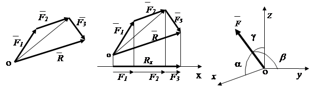
Fig.1.19 Fig.1.20. Fig.1.21.
Analytically, the resultant force can be determined through its projections on the coordinate axes
![]() , (1.5)
, (1.5)
According to the theorem: the projection of the resultant on the axis is equal to the sum of the projections of the terms of the forces on this axis (Fig. 1.20). R x = F 1 x + F 2 x + F 3 x, or in general
R x = å F kx (1.6)
Taking into account (1.6), the resultant is determined by the expression
The direction of the resultant vector is determined by the cosines of the angles between the vector and the axes x , y, z(fig.1.20)
1.7.2. Transformation of an arbitrary system of forces .
It is impossible to apply the parallelogram rule of forces directly to an arbitrary system of forces, since the lines of action of the forces do not intersect at one point. Previously, the system of forces is brought to one center on the basis of the theorem on the parallel transfer of force.
Theorem: a force applied to a rigid body can, without changing its action, be transferred in parallel to another point of the body, while adding a pair of forces with a moment equal to the moment of the transferred force relative to the point to which it is transferred (Fig. 1.22).
As a result of this transformation, a converging system of forces and the sum of the moments of pairs of forces are obtained. The action of the converging system of forces is replaced by the action of the total force, the action of the moments - by the total moment. The total vector * is called main vector force systems, total moment * - highlight force systems.
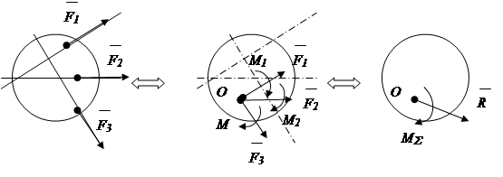
Fig.1.22
Conclusion: an arbitrary system of forces as a result of an identical transformation is reduced to the main vector * and main point * force systems.
Analytically main vector and the main moment of the system of forces can be determined through their projections on the coordinate axes
1.8 Conditions for the equilibrium of systems of forces
1.8.1. Equilibrium of a system of converging forces
By definition (see clause 1.1), the action of a system of converging forces is equivalent to the action of one resultant force. For the equilibrium of the body, it is necessary and sufficient that the resultant equals zero = 0.
It follows from formula (1.7) that for the equilibrium of a spatial system of converging forces it is necessary and sufficient that the sum of the projections of all forces onto axes X,Y,Z was equal to zero
å F kx = 0
å Fky= 0 (1.10) F k z = 0
For the equilibrium of a flat converging system of forces, it is necessary and sufficient that the sum of the projections of all forces on the X, Y axes is equal to zero
å F kx = 0
å Fky = 0 (1.11)
1.8.2. Equilibrium of an arbitrary system of forces.
The action of an arbitrary system of forces is equivalent to the action of the main vector and the main moment. For equilibrium, it is necessary and sufficient that the condition
For the equilibrium of an arbitrary system of forces, it is necessary and sufficient that the sum of the projections of all forces on the X, Y, Z axes and the sum of the moments of all forces relative to axes X,Y,Z were equal to zero.
å F kx = 0
å Fky = 0
å Fkz = 0 (1.13)
å M x(k) = 0
å M y(k) = 0
å M z(k) = 0
For the equilibrium of a flat arbitrary system of forces, it is necessary and sufficient that the sum of the projections of the main vector on the X, Y axes, and the algebraic sum of the moments of forces relative to the center O are equal to zero.
åF ky = 0 (1.14)
EM o ( k) = 0
1.9. Questions for self-control in the section
1. Give a definition of an absolutely rigid body, a material point, a force, a line of action of a force, a system of forces (flat, spatial, converging) of an arbitrary system of forces.
2. What is called the projection of force on the axis, on the plane?
3. What is called the moment of force, how is the moment of force relative to a point determined?
4. Does the moment of force change relative to a given point when the force is transferred along the line of its action?
5. In what case is the moment of force relative to a given point equal to zero?
6. What system of forces is called a pair of forces, what is the moment of a pair of forces?
7. What is called a connection? What is the principle of liberation from bonds? List the main types of connections, show their reactions.
8. What are the conditions and equations for the equilibrium of a system of converging and arbitrary systems of forces located in space and in a plane?
9. Formulate the procedure for solving problems of statics.
2. Kinematics
Kinematics- a branch of theoretical mechanics, which considers the general geometric properties of mechanical motion, as a process occurring in space and time. Moving objects are treated as geometric points or geometric bodies. Accordingly, the study is divided into point kinematics and rigid body kinematics
2.1 Basic concepts of kinematics
The law of motion of a point (body)- dependence of the position of a point (body) in space on time.
Point trajectory- the locus of positions of a point in space during its movement.
Point (body) speed- a characteristic of the change in time of the position of a point (body) in space.
Point (body) acceleration- characteristic of time change in the speed of a point (body)
2.2. Point kinematics
2.2.1 Methods for specifying point movement
To set the movement of a point means to set a change in its position with respect to the chosen reference system. There are three main reference systems: vector, coordinate, natural. Accordingly, there are three ways to specify the movement of a point.
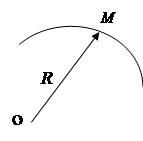
In a vector system, the position of a point relative to the origin is given by the radius vector (Fig. 2.1). Law of motion
The position of a point in the OXYZ coordinate system is given by three X,Y,Z coordinates(fig.2.2). The law of motion x = x ( t ), y = y ( t ), z = z ( t ).
The position of a point in the natural reference system is given by the distance S from the origin to this point along the trajectory (Fig. 2.3). The law of motion s = s ( t ).
 |
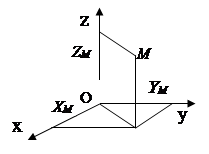 |
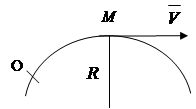
Fig.2.1 Rice. 2.2 Fig.2.3
The movement of a point in the natural way of specifying the movement is determined if the following are known:
1. Trajectory of movement.
2. Beginning and direction of counting of the arc coordinate.
3. Equation of motion.
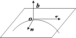
With the natural method of specifying motion, unlike other methods, movable coordinate axes are used, moving along with the point along the trajectory. Such axes are (Fig. 2.4).
Tangent () - directed in the direction of increasing arc coordinates tangentially to the trajectory.
Principal normal ( P) is directed towards the concavity of the curve.
Binormal ( in) is directed perpendicular to the axes t, n.
 |
Rice. 2.4
2.2.2 Determination of the kinematic characteristics of a point
Point trajectory
In the vector reference system, the trajectory is described by the expression
In the coordinate reference system, the trajectory is determined according to the law of point motion and is described by the expressions z = f ( x , y ) - in space, or y = f(x) - in the plane.
In a natural reference system, the trajectory is predetermined.
Point speed
According to the definition (see paragraph 2.1), speed characterizes the change in time of the position of a point (body) in space.
Determining the speed of a point in a vector coordinate system
When specifying the movement of a point in a vector coordinate system, the ratio of movement to a time interval is called the average value of the speed in this time interval.
Taking the time interval as an infinitesimal value, the value of the speed is obtained in this moment time (instantaneous speed value)
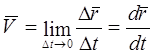 (2.1)
(2.1)
The average velocity vector is directed along the vector in the direction of the point movement, the instantaneous velocity vector is directed tangentially to the trajectory in the direction of the point movement (Fig. 2.5).
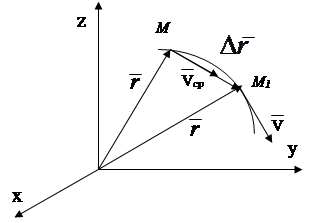 |
Fig.2.5
Conclusion: the speed of a point is a vector quantity equal to the derivative of the law of motion with respect to time.
We note and use in further reasoning the following property of the derivative : the time derivative of a quantity determines the rate of change of that quantity.
Determining the speed of a point in a coordinate reference system
Based on the property of the derivative, we determine the rate of change of the coordinates of the point
The module of the full speed of a point with a rectangular coordinate system will be equal to
![]() (2.3)
(2.3)
The direction of the velocity vector is determined by the cosines of the steering angles
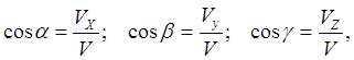
where are the angles between the velocity vector and the coordinate axes.
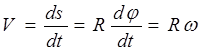
Determining the speed of a point in a natural reference system
The speed of a point in a natural reference system is defined as the derivative of the law of motion of a point
V = (2.4)
According to the previous conclusions, the velocity vector is directed tangentially to the trajectory in the direction of the point movement and in the axes n.b. determined by only one projection.
point acceleration
By definition, acceleration characterizes the change in speed, i.e. rate of change of speed.
Accelerations of a point in a vector frame of reference
Based on the property of the derivative
The velocity vector can change in magnitude and direction. To determine the increment of a vector, we match the beginnings of vectors (Fig.2.6). The acceleration vector is directed along the line of increment of the velocity vector, i.e., towards the curvature of the trajectory.
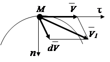
Fig.2.6
Acceleration of a point in a coordinate reference system
The acceleration of change in the coordinates of a point is equal to the time derivative of the rates of change of these coordinates
a x =; a y =; a z = .
The total acceleration in a rectangular coordinate system will be determined by the expression
a
= ![]() , (2.6)
, (2.6)
Direction cosines of the acceleration vector
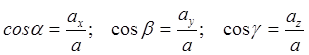 .
.
Acceleration of a point in natural reference system
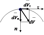
The increment of the velocity vector (Fig. 2.7) can be decomposed into components parallel to the axes natural system coordinates
![]() , (2.7)
, (2.7)
Dividing the left and right sides of equality (2.7) by dt, we get
![]() , (2.8)
, (2.8)
where: - tangential acceleration, (2.9)
Normal acceleration, (see derivation, item 43)
where R is the radius of curvature of the trajectory in the vicinity of the point
 |
Rice. 2.7
2.3. Rigid Body Kinematics
In contrast to the kinematics of a point, two main tasks are solved in the kinematics of rigid bodies:
Setting the movement and determining the kinematic characteristics of the body as a whole;
Determination of kinematic characteristics of body points.
Methods for setting and determining kinematic characteristics depend on the types of motion of bodies.
In this manual, three types of motion are considered: translational, rotational around a fixed axis and plane-parallel motion of a rigid body
2.3.1. Translational motion of a rigid body
Translational is a movement in which a straight line drawn through two points of the body remains parallel to its original position (Fig. 2.8).
Theorem proved: in translational motion, all points of the body move along the same trajectories and at each moment of time have the same speed and acceleration in absolute value and direction (Fig. 2.8).
Conclusion: The translational motion of a rigid body is determined by the motion of any of its points, and therefore, the task and study of its motion is reduced to the kinematics of a point.
 |
Rice. 2.8 Fig. 2.9
2.3.2 Rotational motion of a rigid body around a fixed axis.
Rotational around a fixed axis is the movement of a rigid body, in which two points belonging to the body remain stationary during the entire time of movement.
The position of the body is determined by the angle of rotation j (Fig. 2.9). The unit of measurement for an angle is radians. (radian - central corner a circle whose arc length is equal to the radius, full angle circle contains 2p radians.)
The law of rotational motion of a body around a fixed axis j = j(t). The angular velocity and angular acceleration of the body will be determined by the differentiation method
Angular velocity, rad/s; (2.10)
Angular acceleration, rad/s 2 (2.11)
At rotary motion bodies around a fixed axis, its points that do not lie on the axis of rotation move in circles centered on the axis of rotation.
If we cut the body by a plane perpendicular to the axis, choose a point on the axis of rotation FROM and arbitrary point M, then point M will describe around the point FROM radius circle R(Fig. 2.9). During dt there is an elementary rotation through the angle , while the point M will move along the trajectory for a distance. Let's determine the linear velocity module:
 (2.12)
point acceleration M for a known trajectory is determined by its components, see (2.8)
![]() ,
,
Substituting expression (2.12) into the formulas, we get:
 , .
, . , (2.13)
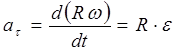
where: - tangential acceleration,
Normal acceleration.
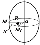
2.3.3. Plane-parallel motion of a rigid body
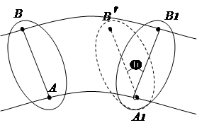
Plane-parallel is the movement of a rigid body, in which all its points move in planes parallel to one fixed plane (Fig. 2.10). To study the motion of a body, it is sufficient to study the motion of one section S this body by a plane parallel to the fixed plane. Section movement S in its plane can be considered as a complex one, consisting of two elementary movements: a) translational and rotational; b) rotational relative to the mobile (instantaneous) center.
In the first variant the movement of the section can be given by the equations of motion of one of its points (the pole) and the rotation of the section around the pole (Fig. 2.11). Any point of the section can be taken as a pole.
 |
 |
Rice. 2.10 Fig. 2.11
The equations of motion will be written as:
X A = X A ( t )
Y BUT = Y BUT ( t ) (2.14)
j BUT = j BUT ( t )
The kinematic characteristics of the pole are determined from the equations of its motion.
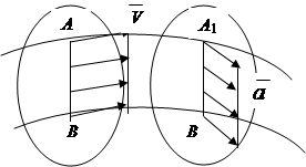
The speed of any point of a plane figure moving in its own plane is the sum of the speed of the pole (arbitrarily chosen in the section of the point BUT) and the speed of rotation around the pole (rotation of the point AT around the dot BUT).
The acceleration of a point of a moving flat figure is the sum of the acceleration of the pole relative to the fixed frame of reference and the acceleration due to rotational motion around the pole.
![]() (2.15)
(2.15)
![]() (2.16)
(2.16)
In the second variant the movement of the section is considered as rotational around the movable (instantaneous) center P(Fig. 1.12). In this case, the speed of any point B of the section will be determined by the formula for rotational motion
![]() (2.17)
(2.17)
Angular velocity around the instantaneous center R can be determined if the speed of any point of the section is known, for example, point A.
 (2.18)
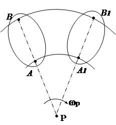
Fig.2.12
The position of the instantaneous center of rotation can be determined based on the following properties:
The point's velocity vector is perpendicular to the radius;
The speed module of a point is proportional to the distance from the point to the center of rotation ( V = w ∙ R) ;
The speed at the center of rotation is zero.
Let us consider some cases of determining the position of the instantaneous center.
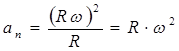
1. The directions of the velocities of two points of a flat figure are known (Fig. 2.13). Let's draw lines of radii. Instant center of rotation R located at the intersection of perpendiculars drawn to the velocity vectors.
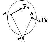
2. The speeds of points A and B are known, and the vectors and are parallel to each other, and the line AB perpendicular (Fig. 2. 14). In this case, the instantaneous center of rotation lies on the line AB. To find it, we draw a line of proportionality of velocities based on the dependence V = w R .
3. The body rolls without slipping on the fixed surface of another body (Fig. 2.15). The point of contact of the bodies at the moment has zero speed, while the speeds of other points of the body are not equal to zero. touch point R will be the instantaneous center of rotation.
 |
 |
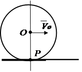 |
Rice. 2.13 Rice. 2.14 Rice. 2.15
In addition to the options considered, the speed of a section point can be determined on the basis of the theorem on the projections of the velocities of two points of a rigid body.
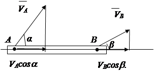
Theorem: the projections of the velocities of two points of a rigid body onto a straight line drawn through these points are equal and equally directed .
Proof: Distance AB cannot change, therefore
V And cosa can't be more or less V In cosb (Fig. 2.16).
 |
||
Rice. 2.16
Conclusion: V BUT cosa= V AT cosb. (2.19)
2.4. Complex point movement
In the previous paragraphs, the motion of a point relative to a fixed frame of reference, the so-called absolute motion, was considered. In practice, there are problems in which the movement of a point relative to a coordinate system is known, which moves relative to a fixed system. In this case, it is required to determine the kinematic characteristics of the point relative to the fixed system.
It is customary to call: the movement of a point relative to a moving system - relative, the movement of a point together with the moving system - portable, the motion of a point relative to a fixed system - absolute. Accordingly, the speeds and accelerations are called:
Relative; - figurative; -absolute.
According to the velocity addition theorem, the absolute velocity of a point is equal to vector sum relative and portable speeds (Fig.).
![]() , (2.20)
, (2.20)
The absolute value of the speed is determined by the law of cosines
![]() , (2.21)
, (2.21)
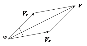
Fig.2.17
Acceleration according to the parallelogram rule is determined by only in translational motion
![]() , (2.22)
, (2.22)
With non-translational portable motion, a third component of acceleration appears, called rotary or Coriolis.
![]() , (2.23)
, (2.23)
where ![]()
Coriolis acceleration is numerically equal to
![]() ,
,
where a is the angle between the vectors and
It is convenient to determine the direction of the Coriolis acceleration vector according to N.E. Zhukovsky: project the vector onto a plane perpendicular to the axis of translational rotation, rotate the projection by 90 degrees in the direction of translational rotation. The resulting direction will correspond to the direction of the Coriolis acceleration.
2.5 Questions for self-control in the section
1. What are the main tasks of kinematics? Name the kinematic characteristics.
2. Name the methods for specifying the movement of a point and determining the kinematic characteristics.
3. Give a definition of translational, rotational around a fixed axis, plane-parallel motion of a body.
4. How is the motion of a rigid body specified during translational, rotational around a fixed axis and plane-parallel motion of the body, and how is the speed and acceleration of a point determined during these motions of the body?
3. Dynamics
3.1 Problems of dynamics
Two types of problems are solved in dynamics. The first is to define active forces given the law of motion of a material object (point or system). The second task is the reverse of the first: the law of motion of a material object is determined with known forces acting on it.
3.2. Basic concepts of dynamics
inertia- the property of material bodies to maintain a state of rest or uniform rectilinear motion until external forces change this state.
Weight- a quantitative measure of the inertia of the body. The unit of mass is the kilogram (kg).
Material point- a body with a mass, the dimensions of which are neglected when solving this problem.
Center of mass of a mechanical system- a geometric point whose coordinates are determined by formulas.
where m k , x k , y k , z k- mass and coordinates of k - that point of the mechanical system,
m is the mass of the system.
In a uniform field of gravity, the position of the center of mass coincides with the position of the center of gravity.
Moment of inertia of a material body about the axis is a quantitative measure of inertia during rotational motion.
The moment of inertia of a material point about the axis is equal to the product of the mass of the point and the square of the distance of the point from the axis.
J Z = m × r 2 (3.2)
The moment of inertia of the system (body) about the axis is equal to the arithmetic sum of the moments of inertia of all points.
J Z = å m k × rk 2 (3.3)
The force of inertia of a material point- a vector quantity equal in absolute value to the product of the mass of a point and the module of acceleration and directed opposite to the acceleration vector
![]() (3.4)
(3.4)
Force of inertia of a material body- a vector quantity equal in absolute value to the product of the body mass and the module of acceleration of the center of mass of the body and directed opposite to the acceleration vector of the center of mass
![]() ,
(3.5)
,
(3.5)
where is the acceleration of the center of mass of the body.
Elemental Force Impulse- vector quantity equal to the product of the force vector by an infinitesimal time interval dt
![]() , (3.6)
, (3.6)
Total impulse force for D t is equal to the integral of elementary impulses
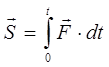 (3.7)
(3.7)
elementary work strength- scalar value dA, equal to the scalar product of the force vector and the infinitesimal displacement d .
The scalar product of vectors is equal to the product of their modules and the cosine of the angle between the directions of the vectors.
dA = F × ds × cos a , (3.8)
where a is the angle between the directions of the displacement and force vectors.
The work of the force on the final displacement of the point of its application is equal to the integral of the elementary work, taken over the displacement.
 (3.9)
(3.9)
The unit of work is Joule (1 J=1 N×m).
Quantity of movement of a material point- a vector quantity equal to the product of the mass m and its speed.
The momentum of a mechanical system is equal to the vector sum of the momentum of its points.
![]() (3.11)
(3.11)
or taking into account formulas (3.1).
where: m is the mass of the mechanical system,
The velocity vector of the center of mass of the system.
Kinetic energy of a material point- scalar value T, equal to half the product of the mass of the point and the square of its speed.
T = (3.13)
The kinetic energy of a mechanical system is equal to the sum kinetic energies all its points.
3.3. Axioms of dynamics
The first axiom is the law of inertia .
If no forces act on a free material point or a balanced system of forces acts, then the point will be at rest or uniform rectilinear motion.
The second axiom is the law of proportionality of acceleration .
The acceleration imparted to a material point by the force acting on it is proportional to this force and coincides in direction with the direction of the force.
Expression (3.15) is called basic law of dynamics .
The third axiom is the law of counteraction .
The forces with which two material points act on each other are equal in absolute value and directed along the straight line connecting these points in opposite directions
The fourth axiom is the law of independence of the action of forces .
When a system of forces acts on a material point, the total acceleration of this point is equal to the geometric sum of the accelerations from the action of each force
3.4. Differential Equations of Dynamics
The differential equations of motion of a point relate the acceleration of a point to the forces acting on it. In fact, differential equations are a record of the basic law of dynamics in an explicit differential form.
For the absolute motion of a point (motion in an inertial frame of reference), the differential equation has the form
 , (3.18)
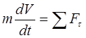
The vector equation (3.17) can be written in projections on the axes of a rectangular inertial coordinate system
![]() ,
,
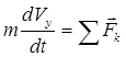 , (3.19)
![]() ,
,
With a known trajectory of the point, equation (3.18) can be written in projections on the axes of the natural coordinate system
![]() , (3.20)
, (3.20)
![]()
Taking into account (2.8), the equations take the form
 (3.21)
3.5 General theorems of dynamics
General theorems of dynamics establish the relationship between the measures of mechanical motion and mechanical interaction. The conclusions of the theorems are the result of an identical transformation of the basic law of dynamics.
Theorem on the change in momentum : the change in the momentum of a material point (mechanical system) over a finite period of time is equal to the sum of impulses external forces for the same period of time
![]() - for a material point; (3.22)
- for a material point; (3.22)
![]() - for the mechanical system. (3.23)
- for the mechanical system. (3.23)
Kinetic energy change theorem : the change in the kinetic energy of a point (mechanical system) during its movement is equal to the sum of the work of all acting external forces on this movement
 - for a material point (3.24)
![]() - for a mechanical system (3.25)
- for a mechanical system (3.25)
The kinetic energy of a mechanical system is determined in accordance with (3.14), while the following dependences are derived for solids
With the translational motion of the body, (3.26)
During the rotational motion of the body, (3.27)
 - with a plane-parallel movement of the body. (3.28)
Moments of inertia of some homogeneous bodies
 |
Rice. 3.1 Fig.3.2. R Figure 3.3.
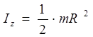
The moment of inertia of the cylinder relative to the axis (Fig. 3.1.)
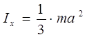
Moment of inertia of the rod about the z-axis (Fig. 3.2)
![]()
Moment of inertia of a rectangular plate about the x and y axes (Fig. 3.3)
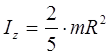
The moment of inertia of the ball is determined by the formula:
In the general case, the work of forces is determined in accordance with (3.8), (3.9). In a number of cases of the action of forces, the work can be determined by particular dependencies.
The work of gravity
where: - gravity,
Change in body position vertically.
The work of force during the rotational movement of the body
, (3.30)
where: - moment of force,
Angular velocity of the body.
Keep in mind that work, as a scalar quantity, can be positive or negative. The work will be positive if the direction of the force coincides with the direction of motion.
3.6 d'Alembert principle
The above methods for studying the motion of bodies are based on Newton's laws. Methods based on other principles have been developed. One of them is d'Alembert's principle.The principle is formulated: if at any moment of time the forces of inertia are added to the forces acting on the point, then the resulting system of forces will be balanced
![]() , (3.31)
, (3.31)
or for mechanical system
![]()
The d'Alembert principle makes it possible to apply to solving problems of dynamics more simple methods statics, so it is widely used in engineering practice.
3.7. Questions for self-control in the section
1. Formulate the main tasks of dynamics.
2. Give definitions of mass, moment of inertia, impulse of force, work of force, momentum, kinetic energy.
3. Formulate the basic laws of dynamics.
4. What equation is called differential equation speakers? What is the algorithm for solving problems of dynamics using differential equations?
5. Formulate general theorems of dynamics.
6. Formulate the d'Alembert principle. How are inertia forces determined?
7. Formulate the principle of possible movements. Under what conditions does the principle of possible displacements apply?
In this chapter, problems are considered for determining the work done by a constant force and the developed power during the translational and rotational motion of bodies (E. M. Nikitin, § 81-87).
§ 44. Work and power in translational motion
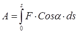
The work of a constant force P on a straight section of the path s, traversed by the point of application of the force, is determined by the formula
(1) A = Ps cos α,
where α is the angle between the direction of the force and the direction of movement.
At α = 90°
cos α = cos 90° = 0 and A = 0,
i.e., the work of a force acting perpendicular to the direction of movement is zero.
If the direction of the force coincides with the direction of movement, then α = 0, therefore cos α = cos 0 = 1 and formula (1) is simplified:
(1") A = Ps.
Not one force, but several, usually acts on a point or on a body, therefore, when solving problems, it is advisable to use the theorem on the operation of the resultant system of forces (E. M. Nikitin, § 83):
(2) A R = ∑ A i ,
i.e., the work of the resultant of any system of forces on a certain path is equal to the algebraic sum of the work of all the forces of this system on the same path.
In a particular case, when the system of forces is balanced (the body moves uniformly and in a straight line), the resultant of the system of forces is equal to zero and, therefore, A R =0. Therefore, with a uniform and rectilinear motion of a point or body, equation (2) takes the form
(2") ∑ Ai = 0,
i.e., the algebraic sum of the work of a balanced system of forces on a certain path is equal to zero.
In this case, the forces whose work is positive are called driving forces, and the forces whose work is negative are called resistance forces. For example, when the body moves down - gravity - driving force and its work is positive, and when the body moves upwards, its gravity is a resistance force and the work of gravity is negative.
When solving problems in cases where the force P is unknown, the work of which needs to be determined, two methods (methods) can be recommended.
1. Using the forces specified in the condition of the problem, determine the force P, and then use the formula (1) or (1") to calculate its work.
2. Without directly determining the force P, determine A p - the work of the required force using formulas (2) and (2"), expressing the theorem on the work of the resultant.
The power developed during the work of a constant force is determined by the formula
(3) N = A/t or N = (Ps cos α)/t.
If, when determining the work of the force P, the speed of the point v \u003d s / t remains constant, then
(3") N = Pv cos α.
If the speed of the point changes, then s / t \u003d v cf - average speed and then formula (2") drops out the average power
N av = Pv av cos α.
Coefficient useful action(k.p.d.) when doing work can be defined as the ratio of work
(4) η = A field /A,
where A floor - useful work; A is all the work done, or as a ratio of the respective capacities:
(4") η = N floor /N.
The SI unit of work is 1 joule (J) = 1 N * 1 m.
The SI unit of power is 1 watt (W) = 1 J / 1 sec.
A popular off-system unit of power is horsepower (hp):
1000 W = 1.36 liters. With. or 1 l. With. = 736 W.
To switch between watts and horsepower, use the formulas
N (kW) = 1.36 N (hp)
N (hp) \u003d 0.736 N (kW).
Lecture 2. Work. Power. Theorem on the change in the kinetic energy of a point.
This lecture covers the following questions:
Force work.
Power.
Work calculation examples.
Potential energy
Kinetic energy
Theorem on the change in the kinetic energy of a point.
The moment theorem.
The study of these issues is necessary for the dynamics of the center of mass of a mechanical system, the dynamics of the rotational motion of a rigid body, the kinetic moment of a mechanical system, for solving problems in the disciplines "Theory of machines and mechanisms" and "Machine parts".
Force work. Power.
To characterize the action exerted by a force on a body with some displacement, the concept of the work of a force is introduced.
Fig.16
In this case, the work characterizes the action of the force, which determines the change module the speed of the moving point.
Let us first introduce the concept of the elementary work of a force on an infinitesimal displacement ds. The elementary work of a force (Fig. 16) is a scalar quantity:
where is the projection of the force on the tangent to the trajectory directed in the direction of the point displacement, and is the infinitely small displacement of the point directed along this tangent.
This definition corresponds to the concept of work, as a characteristic of the action of a force that leads to a change in the modulus of the speed of a point. Indeed, if we decompose the force into components and , then only the component will change the modulus of the point's velocity, imparting a tangential acceleration to the point. The component or changes the direction of the velocity vector v(gives a normal acceleration to the point), or, if the movement is not free, it changes the pressure on the connection. The component will not affect the speed modulus, i.e., as they say, the force "will not produce work."
Noticing that , we get:
![]() . (1)
. (1)
In this way, elementary work force is equal to the projection of the force on the direction of movement of the point, multiplied by the elementary displacement, or the elementary work of the force is equal to the product of the modulus of force by the elementary displacement and the cosine of the angle between the direction of the force and the direction of displacement.
If the angle is acute, then the work is positive. In particular, for elementary work .
If the angle is obtuse, then the work is negative. In particular, for elementary work .
If the angle , i.e. if the force is directed perpendicular to the displacement, then the elementary work of the force is zero.
Let us find an analytical expression for the elementary work. To do this, we decompose the force into components , , in the directions of the coordinate axes (Fig. 17; the force itself is not shown in the drawing).
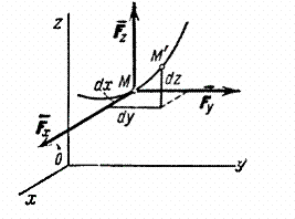
Fig.17
An elementary displacement is composed of displacements , , along the coordinate axes, where x, y, z - point coordinates M. Then the work of the force on displacement can be calculated as the sum of the work of its components , , on displacements , , .
But only the component does work on the displacement, and its work is equal to . Work on displacements and is calculated similarly. Finally we find:
The formula gives an analytical expression for the elementary work of a force.
The work done by a force in any finite displacement M 0 M 1 is calculated as the integral sum of the corresponding elementary works and will be equal to:
![]() or
or
![]() .
.
Consequently, work of force on any displacement M 0 M 1 is equal to the integral of the elementary work taken along this displacement. The limits of the integral correspond to the values of the integration variables at the points M 0 and M 1 .
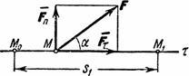
Fig.18
If the value is constant (= const), then denoting the displacement M 0 M 1 through we get: .
Such a case can take place when the acting force is constant in modulus and direction ( F= const), and the point to which the force is applied moves in a straight line (Fig. 18). In this case ![]() and the work of the force
and the work of the force ![]() .
.
The SI unit for work is joule (1 j = 1 hm).
Power.
Power is the quantity that determines the work done by the force per unit time. If the work is done evenly, then the power
where t - the time during which the work was done A. In general
![]() .
.
Therefore, the power is equal to the product of the tangential component of the force and the speed of movement.
The unit of power in the system SI is watt (1 Tue= 1 j/sec). In engineering, 1 horsepower is often taken as a unit of power, equal to 75 kGm/sec or 736 Tue.
The work done by a machine can be measured by the product of its power and the time it has been running. From this arose the unit of measurement of work, kilowatt-hour, commonly used in technology (1 kWh = 3,6j 367100 kGm).
It can be seen from the equation that for an engine with a given power W, the traction force will be the greater, the lower the speed of movement V. Therefore, for example, on a rise or on a bad section of the road, the car includes lower gears, which allow, at full power, to move at a lower speed and develop more traction.
Work calculation examples.
The examples considered below give results that can be directly used in solving problems.
1) The work of gravity. Let the point M, on which the force of gravity acts , moves from position M 0 (x 0 , at 0 , z 0 ) into position M 1 (X 1 , y 1 , z 1 ). We choose the coordinate axes so that the axis Oz was directed vertically upwards (Fig. 19).
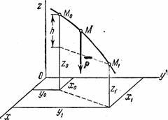
Fig.19
Then R x=0, R y=0, P z=- R. Substituting these values and considering the integration variable z:
If point M 0 above M 1 , where h- the value of the vertical movement of the point;
If the point M 0 below point M 1 then .
Finally we get: ![]() .
.
Consequently, the work of gravity is equal to the product of the modulus of force, taken with a plus or minus sign, and the vertical displacement of the point of its application. The work is positive if the start point is higher than the end point, and negative if the start point is lower than the end point. It follows from the result obtained that the work of gravity does not depend on the type of the trajectory along which the point of its application moves.
Forces with this property are called potential forces.
2) The work of the elastic force. Consider the cargo M, lying on a horizontal plane and attached to the free end of some spring (Fig. 20a). Mark on the plane with a dot O the position occupied by the end of the spring when it is not stressed ( is the length of the unstressed spring), and we take this point as the origin. If we now pull the load away from the equilibrium position O, extending the spring to a value , then the load will be acted upon by the elastic force of the spring F, directed to the point O.
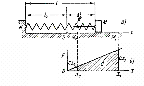
Fig.20
According to Hooke's law, the magnitude of this force is proportional to the elongation of the spring. Since in our case , then modulo .
Coefficient With called stiffness factor springs. In engineering, one usually measures With in h/cm, assuming coefficient With numerically equal to the force that must be applied to the spring to stretch it by 1 cm.
Find the work done by the elastic force when moving the load from position to position .
Since in this case ![]() , , then we get:
, , then we get:
(The same result can be obtained from the dependency graph F from X (fig.20, b) calculating the area of the trapezoid shaded in the drawing and taking into account the sign of work.) In the resulting formula, represents the initial elongation of the spring, and end extension of the spring. Consequently,
![]() ,
,
those. the work of the elastic force is equal to half the product of the stiffness coefficient and the difference between the squares of the initial and final elongations (or compressions) of the spring.
The work will be positive when , i.e. when the end of the spring moves to the equilibrium position, and negative when , i.e. the end of the spring moves away from the equilibrium position. It can be proved that the formula remains valid even in the case when the displacement of the point M is not linear.
Thus, it turns out that the work of the force F depends only on the values and and does not depend on the type of point trajectory M. Therefore, the elastic force is also potential.
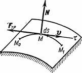
Fig.21
3) The work of the friction force. Consider a point moving along some rough surface (Fig. 21) or a curve. The friction force acting on the point is equal in absolute value fN, where f is the coefficient of friction, and is the normal reaction of the surface. The friction force is directed opposite to the displacement of the point. Consequently, F tr = - fN and according to the formula
![]() .
.
If the friction force is constant, then ![]() ,
where s-curve arc length M 0 M 1 along which the point moves.
,
where s-curve arc length M 0 M 1 along which the point moves.
In this way, The work done by the sliding friction force is always negative. The amount of this work depends on the length of the arc M 0 M 1 . Therefore, the force of friction is the force non-potential.
4) The work of a force applied to a body rotating about a fixed axis.
In this case (Fig. 22), the force application point moves along a circle of radius r. Elementary work, by (1), ![]() , where .
, where .
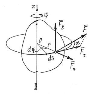
Fig.22
That's why ![]() .
.
This is not difficult to establish by decomposing the force into three components (Fig. 22). (Moments of forces and are equal to zero). Means,
![]() (2)
(2)
In particular, if the moment of force about the axis ![]() , the work of the force when the body rotates through an angle is equal to
, the work of the force when the body rotates through an angle is equal to
![]() . (3)
. (3)
The sign of work is determined by the signs of the moment of force and the angle of rotation. If they are the same, the work is positive.
Formula (3) also implies the rule for determining the work of a pair of forces. If a couple with a moment m is located in a plane perpendicular to the axis of rotation of the body, then its work when the body rotates through an angle
If a pair of forces acts in a plane not perpendicular to the axis of rotation, then it must be replaced by two pairs. One is placed in the plane perpendicular to the axis, the other - in the plane parallel to the axis. Their moments are determined by the expansion of the moment vector in the corresponding directions: . Of course, only the first pair with the moment will do the work, where is the angle between the vector and the axis of rotation z,
![]() . (5)
. (5)
Potential energy
The part of space in which a force acting on a material point placed there, depending on the location of the point, is called a force field.
Moreover, this force is determined using the force function u = u(x, y, z). If it does not depend on time, then such a field is called stationary. If it is the same at all points, then the field is homogeneous.
If the projections of the force on the Cartesian axes are partial derivatives of the force function with respect to the corresponding coordinates
then such a field is called potential.
Calculate the work of force potential field when moving a point from a position M 1 to position M 2. (Fig. 23).
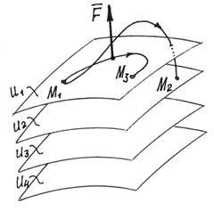
Fig.23
elementary work,
This is the total differential of the force function.
Working on final travel
![]() (7)
(7)
where u 2 and u 1 – strength function values at points M 2 and M 1 .
Consequently, the work of the potential field force does not depend on the trajectory of the point, but is determined only by the values of the force function in the initial and final positions of the point.
Naturally, if the point returns to its initial position, the work of the force will be zero. The work will be equal to zero and when moving to another point M 3 if the value of the force function there is the same as in the initial position.
It is easy to guess that points with the same values of the force function will form an entire surface. And that the force field is a layered space consisting of such surfaces (Fig. 23). These surfaces are called level surfaces or equipotential surfaces. Their equations are: u(x, y, z)= C (C- constant, equal to value u points on this surface). And the force function is called, respectively, potential fields.
Of course, the equipotential surfaces do not intersect. Otherwise, there would be field points with an indefinite potential.
Since, when moving a point along an equipotential surface, the work of the force is zero, then the force vector is perpendicular to the surface.
Among these surfaces, we choose one and call it the zero surface (we put u= u 0 ).
The work that the force will do when the point moves from a certain place M to the zero surface is called the potential energy of the point at this specific place M:
![]() . (8)
. (8)
notice, that potential energy at the same point of the field depends on the choice of the null surface.
By (8) force function . Therefore, the force projections on the Cartesian axes, according to (6), since ,
and force vector ![]() .
.
Consider several potential fields.
1) Gravity field.
Near the surface of the Earth, the force of gravity at all points is the same, equal to the weight of the body. This means that this force field is homogeneous. Since when a point moves in a horizontal plane, the work of the force is zero, the equipotential surfaces will be horizontal planes (Fig. 24), and their equations: u = z = C.
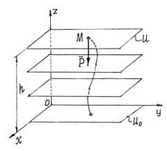
Fig.24
If the plane is assigned as the zero surface xOy, then the potential energy of a point in position M will be equal to the work of gravity:
2) The field of elastic force.
When an elastic body, such as a spring, is deformed, a force appears. That is, a force field arises near this body, the forces of which are proportional to the deformation of the body and directed towards the undeformed state. At the spring - to the point M 0 , where the end of the undeformed spring is located (Fig. 25).
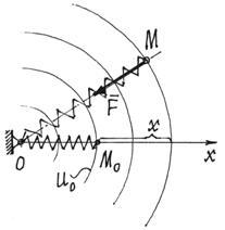
Fig.25
If you move the end of the spring so that its length does not change, then the work of the elastic force will be zero. This means that equipotential surfaces are spherical surfaces centered at the point O.
Assign the zero surface to the sphere passing through the point M 0 , through the end of the undeformed spring. Then the potential energy of the spring in position M: .
With such a choice of the zero surface, the potential energy will always be positive (P>0), both in the stretched and in the compressed state.
Theorem on the change in the kinetic energy of a point.
Consider a point with mass t, moving under the action of forces applied to it from a position M 0 , where it has speed , into position M 1 , where its speed is .
To obtain the desired dependence, we turn to the equation expressing the basic law of dynamics. Projecting both parts of this equality onto the tangent to the point's trajectory M, directed in the direction of motion, we get:
The value of the tangential acceleration on the left can be represented as
![]() .
.
As a result, we will have:
![]() .
.
Multiplying both sides of this equation by ds, we will introduce t under the sign of the differential. Then, noticing that where - elementary work of force F k we obtain the expression of the theorem on the change in kinetic energy in differential form.
The work of gravity. gravity R material point mass t near the Earth's surface can be considered a constant, equal to mg
directed vertically down.
Work BUT strength R on the move from the point M 0 to the point M
where h = z 0 - z x - point lowering height.
The work of gravity is equal to the product of this force and the height of lowering (work is positive) or the height of lifting (work is negative). The work of gravity does not depend on the shape of the trajectory between points M 0 and M|, and if these points coincide, then the work of gravity is equal to zero (the case of a closed path). It is also equal to zero if the points M 0 and M lie in the same horizontal plane.
The work of the linear force of elasticity. The linear elastic force (or linear restoring force) is the force acting according to Hooke's law (Fig. 63):
F = - Withr,
where r- distance from the point of static equilibrium, where the force is zero, to the considered point M; With- constant coefficient - coefficient rigidity.
A=--().
According to this formula, the work of the linear elastic force is calculated. If point M 0 coincides with a dot static balance O, so then r 0 \u003d 0 and for the work of the force on displacement from the point O to the point M we have
Value r- the shortest distance between the considered point and the point of static equilibrium. We denote it by λ and call it a deformation. Then
The work of the linear elastic force on displacement from the state of static equilibrium is always negative and equal to half the product of the stiffness coefficient and the square of the deformation. The work of the linear elastic force does not depend on the form of displacement and the work on any closed displacement is zero. It is also equal to zero if the points Mo and M lie on the same sphere circumscribed from the point of static equilibrium.
The work of a variable force in curvilinear motion.
The work of a force on a curved section
Consider the general case of finding the work of a variable force, the point of application of which moves along a curvilinear trajectory. Let the point M of application of the variable force F move along an arbitrary continuous curve. Denote by the vector of infinitely small displacement of the point M. This vector is directed tangentially to the curve in the same direction as the velocity vector.
Elementary work of a variable force F on an infinitesimal displacement
ds is called the scalar product of the vectors F and ds:
where a- angle between vectors F and ds
That is, the elementary work of the force is equal to the product of the modules of the force vectors and an infinitesimal displacement, multiplied by the cosine of the angle between these vectors.
We decompose the force vector F into two components: - directed along the tangent to the trajectory - and - directed along the normal. line of force
is perpendicular to the tangent to the path along which the point moves, and its work is zero. Then:
dA= Ftds.
In order to calculate the work of the variable force F on the final section of the curve from a to b, one should calculate the integral of elementary work:
Potential and kinetic energy.
Potential energy P matserial point in considerationmy point force field M call work, performed by the forcesla acting on a material point when moving it from a pointMto the starting pointM 0 , i.e.
P = Umm 0
P = =-U=- U
The constant С 0 is the same for all points of the field, depending on which point of the field is chosen as the initial one. It is obvious that potential energy can be introduced only for a potential force field in which the work does not depend on the form of movement between points M and M 0 . A nonpotential force field has no potential energy, and there is no force function for it.
dA = dU= -dP; BUT = U - U 0 = P 0 - P
From the above formulas it follows that P is determined up to an arbitrary constant, which depends on the choice of the starting point, but this arbitrary constant does not affect the forces calculated through the potential energy and the work of these forces. Considering this:
P= - U+ const or P =- U.
The potential energy at any point of the field, up to an arbitrary constant, can be defined as the value of the force function at the same point, taken with a minus sign.
Kinetic energy system is called a scalar value T, equal to the sum of the kinetic energies of all points of the system:
Kinetic energy is a characteristic of both translational and rotational motions of the system. Kinetic energy is a scalar quantity and, moreover, essentially positive. Therefore, it does not depend on the directions of movement of the parts of the system and does not characterize changes in these directions.
Let us also note the following important circumstance. Internal forces act on parts of the system in mutually opposite directions. Changes in kinetic energy are influenced by the action of both external and internal forces.
Uniform motion of a point.
Uniform motion of a point- movement, with Krom kasat. acceleration ω t point (in the case of rectilinear motion, the total acceleration ω )constantly. The law of uniform motion of a point and the law of change in its speed υ during this motion are given by the equalities:
where s is the distance of the point measured along the trajectory arc from the reference point chosen on the trajectory, t- time, s 0 - value of s at the beginning. moment of time t = = 0. - beg. point speed. When the signs υ and ω identical, uniform motion. is accelerated, and when different - slowed down.
When acting. uniform motion of a rigid body, all of the above applies to each point of the body; with uniform rotation around a fixed axis of angle. acceleration e of the body is constant, and the law of rotation and the law of change of angle. the velocities ω of the body are given by the equalities
where φ is the angle of rotation of the body, φ 0 is the value of φ in the beginning. moment of time t= 0, ω 0 - beg. ang. body speed. When the signs of ω and ε match, the rotation is accelerated, and when they do not match, it is slow.
The work of a constant force in rectilinear motion.
Let us define the work for the case when the acting force is constant in magnitude and direction, and the point of its application moves along a rectilinear trajectory. Consider a material point C, to which a force constant in value and direction is applied (Fig. 134, a).
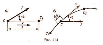
For a certain period of time t, point C has moved to position C1 along a rectilinear trajectory at a distance s.
The work W of a constant force during rectilinear motion of the point of its application is equal to the product of the modulus of force F times the distance s and the cosine of the angle between the direction of the force and the direction of movement, i.e.
The angle α between the direction of the force and the direction of motion can vary from 0 to 180°. For α< 90° работа положительна, при α >90° is negative, at α = 90° the work is zero.
If the force makes an acute angle with the direction of motion, it is called the driving force, the work of the force is always positive. If the angle between the directions of the force and the movement is obtuse, the force resists the movement, performs negative work and is called the resistance force. Examples of resistance forces are the forces of cutting, friction, air resistance, and others, which are always directed in the direction opposite to the movement.
When α = 0°, i.e., when the direction of the force coincides with the direction of the velocity, then W = F s, since cos 0° = 1. The product F cos α is the projection of the force onto the direction of motion of the material point. Therefore, the work of a force can be defined as the product of the displacement s and the projection of the force and the direction of movement of the point.
33. Forces of inertia of a rigid body
In classical mechanics, the representations of forces and their properties are based on Newton's laws and are inextricably linked with the concept of the inertial frame of reference.
Indeed, the physical quantity called force is introduced into consideration by Newton's second law, while the law itself is formulated only for inertial systems reference. Accordingly, the concept of force initially turns out to be defined only for such frames of reference.
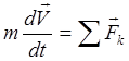
The equation of Newton's second law, which relates the acceleration and mass of a material point with the force acting on it, is written as
It directly follows from the equation that only forces are the cause of acceleration of bodies, and vice versa: the action of uncompensated forces on a body necessarily causes its acceleration.
Newton's third law complements and develops what was said about forces in the second law.
force is a measure of the mechanical action on a given material body of other bodies
in accordance with Newton's third law, forces can only exist in pairs, and the nature of the forces in each such pair is the same.
any force acting on a body has a source of origin in the form of another body. In other words, forces are necessarily the result interactions tel.
No other forces in mechanics are brought into consideration or used. The possibility of the existence of forces that have arisen independently, without interacting bodies, is not allowed by mechanics.
Although the names of the Euler and d'Alembert forces of inertia contain the word strength, these physical quantities are not forces in the sense accepted in mechanics.
34. The concept of plane-parallel motion of a rigid body
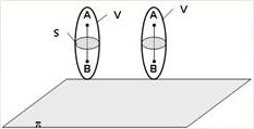
The motion of a rigid body is called plane-parallel if all points of the body move in planes parallel to some fixed plane (the main plane). Let some body V make a plane motion, π - the main plane. From the definition of plane-parallel motion and the properties of an absolutely rigid body, it follows that any line segment AB, perpendicular to the plane π, will make forward movement. That is, the trajectories, speeds and accelerations of all points of the segment AB will be the same. Thus, the movement of each point of the section s parallel to the plane π determines the movement of all points of the body V lying on the segment perpendicular to the section at this point. Examples of plane-parallel motion are: wheel rolling along a straight segment, since all its points move in planes parallel to the plane perpendicular to the wheel axis; a special case of such a movement is the rotation of a rigid body around a fixed axis, in fact, all points of a rotating body move in planes parallel to some fixed plane perpendicular to the axis of rotation.
35. Forces of inertia in the rectilinear and curvilinear motion of a material point
The force with which a point resists a change in motion is called the force of inertia of a material point. The force of inertia is directed opposite to the acceleration of the point and is equal to the mass times the acceleration.
In a straight line the direction of acceleration coincides with the trajectory. The force of inertia is directed in the direction opposite to acceleration, and its numerical value is determined by the formula:
With accelerated movement, the directions of acceleration and speed coincide and the force of inertia is directed in the direction opposite to the movement. In slow motion, when the acceleration is directed in the direction opposite to the speed, the force of inertia acts in the direction of motion.
Atcurvilinear and unevenmovement acceleration can be decomposed into normal an and tangent at components. Similarly, the force of inertia of a point also consists of two components: normal and tangential.
Normal the component of the inertial force is equal to the product of the mass of the point and the normal acceleration and is directed opposite to this acceleration:
![]()
Tangent the component of the inertial force is equal to the product of the mass of the point and the tangential acceleration and is directed opposite to this acceleration:
It's obvious that full strength inertia point M is equal to the geometric sum of the normal and tangent components, i.e.
![]()
Considering that the tangential and normal components are mutually perpendicular, the total inertia force is:
36. Theorems on the addition of velocities and accelerations of a point in complex motion
Velocity addition theorem:
In mechanics, the absolute velocity of a point is equal to the vector sum of its relative and translational velocities:
The speed of the body relative to the fixed frame of reference is equal to the vector sum of the speed of this body relative to the moving frame of reference and the speed (relative to the fixed frame) of the point of the moving frame where the body is located.
in a complex motion, the absolute speed of a point is equal to the geometric sum of the translational and relative speeds. The magnitude of the absolute velocity is determined where α
is the angle between the vectors  and
and  .
.
Acceleration addition theorem ( THEOREM OF CORIOLIS)
acor = aper + afrom + acor
The formula expresses the following Coriolis theorem on the addition of accelerated
rhenium: 1 for complex motion, the acceleration of a point is equal to the geometric
the sum of three accelerations: relative, translational and rotary, or
Coriolis.
acor = 2(ω × vot)
37. d'Alembert principle
d'Alembert's principle for a material point: at each moment of motion of a material point, active forces, reactions of bonds and the force of inertia form a balanced system of forces.
d'Alembert's principle- in mechanics: one of the basic principles of dynamics, according to which, if the forces of inertia are added to the given forces acting on the points of the mechanical system and the reactions of the superimposed bonds, then a balanced system of forces will be obtained.
According to this principle, for each i-th point of the system, the equality
where is the active force acting on this point, is the reaction of the connection imposed on the point, is the force of inertia, numerically equal to the product of the mass of the point and its acceleration and directed opposite to this acceleration ().
In fact, we are talking about the transfer of the term ma from right to left in Newton's second law () performed separately for each of the considered material points and the censure of this term by the d'Alembert force of inertia.
The d'Alembert principle makes it possible to apply simpler methods of statics to solving problems of dynamics, therefore it is widely used in engineering practice, the so-called. kinetostatic method. It is especially convenient to use it to determine the reactions of constraints in cases where the law of the ongoing motion is known or found from the solution of the corresponding equations.
One of the most important concepts in mechanics work force .
Force work
![]()
All physical bodies in the world around us are set in motion by force. If a moving body in the same or opposite direction is affected by a force or several forces from one or more bodies, then they say that work is done .
That is, mechanical work is done by the force acting on the body. So, the traction force of an electric locomotive sets the entire train in motion, thereby making mechanical work. The bicycle is propelled by the muscular strength of the cyclist's legs. Therefore, this force also does mechanical work.
In physics work of force called physical quantity, equal to the product of the modulus of force, the modulus of displacement of the point of application of the force and the cosine of the angle between the vectors of force and displacement.
A = F s cos (F, s) ,
where F modulus of force,
s- movement module .
Work is always done if the angle between the winds of force and displacement is not equal to zero. If the force acts in the opposite direction to the direction of motion, the amount of work is negative.
Work is not done if no forces act on the body, or if the angle between the applied force and the direction of motion is 90 o (cos 90 o \u003d 0).
If the horse pulls the cart, then the muscular force of the horse, or the traction force directed in the direction of the cart, does the work. And the force of gravity, with which the driver presses on the cart, does no work, since it is directed downward, perpendicular to the direction of movement.
The work of a force is a scalar quantity.
SI unit of work - joule. 1 joule is the work done by a force of 1 newton at a distance of 1 m if the direction of force and displacement are the same.
If several forces act on a body or material point, then they talk about the work done by their resultant force.
If the applied force is not constant, then its work is calculated as an integral:
![]()
Power

The force that sets the body in motion does mechanical work. But how this work is done, quickly or slowly, is sometimes very important to know in practice. For the same work can be done in different time. The work that a large electric motor does can be done by a small motor. But it will take him much longer to do so.
In mechanics, there is a quantity that characterizes the speed of work. This value is called power.
Power is the ratio of the work done in a certain period of time to the value of this period.
N= A /∆ t
By definition A = F s cos α , a s/∆ t = v , Consequently
N= F v cos α = F v ,
where F - strength, v speed, α is the angle between the direction of the force and the direction of the velocity.
That is power - is the scalar product of the force vector and the velocity vector of the body.
AT international system SI power is measured in watts (W).
The power of 1 watt is the work of 1 joule (J) done in 1 second (s).
Power can be increased by increasing the force that does the work, or the rate at which this work is done.


