Do-it-yourself jet engine at home. How do I make rocket engines
Of course, we are talking about valve pulsating engines, the principle of operation of which is clear from the figure. The valve at the inlet to the combustion chamber freely passes air into it. Fuel is supplied to the chamber, a combustible mixture is formed. When the spark plug ignites the mixture, the excess pressure in the combustion chamber closes the valve. The expanding gases are directed into the nozzle, creating jet thrust. The movement of combustion products creates a technical vacuum in the chamber, due to which the valve opens and air is sucked into the chamber.
Are aircraft engines loud when landing?
For this purpose, the landing gear and aircraft design have been developed. This is a subjective feeling. At the final approach of landing - the last 10 km - the landing flaps and landing gear were extended. Due to the constant descent, the engines run just above idle speed - so they are correspondingly quiet.
Once the aircraft has landed on the runway, the main speed brakes reduce speed and at the same time the pilots in the cockpit activate the thrust switch, which maintains the braking process by diverting some of the engine power forward and braking.
Unlike a turbojet engine, in a PUVRD the mixture does not burn continuously, but in a pulsed mode. This explains the characteristic low-frequency noise of pulsating motors, which makes them inapplicable in civil aviation. From the point of view of efficiency, PuVRDs also lose to TRDs: despite the impressive thrust-to-weight ratio (after all, PuVRDs have a minimum of parts), the compression ratio in them reaches 1.2:1 at most, so the fuel burns inefficiently.
Until a few years ago, engine power was greatly increased. The redirected air and high speed caused a lot of noise. Currently, the speed of the engines does not rise above idle. As a result, noise is significantly reduced. However, this quickly changed when the engineers themselves learned the trade and pushed development in their own directions. As a result of the split in cold war» there were various events that only met with the collapse of the Soviet Union.
By Western standards, this is a special engine for which there is no comparable. This is a kerosene oxygen engine that provides more than 750 tons of thrust. In space, these are worlds. With comparable fuel, they will provide 20% less speed, but in fact empty solid boosters are about 1.5 times heavier than the kerosene-powered first stage. Only hydrogen engines have the best specific impulse yet reduce thrust at a comparable cost and deal with extremely large volumes and extremely low temperatures of liquid hydrogen.
But PUVRDs are invaluable as a hobby: after all, they can do without valves at all. In principle, the design of such an engine is a combustion chamber with inlet and outlet pipes connected to it. The inlet pipe is much shorter than the outlet. The valve in such an engine is nothing more than a front chemical transformations.
Thus, in the West, this lack of efficiency in the first stage must be compensated by the use of more expensive hydrogen engines in the rest of the rocket. Their own kerosene engines were much more inefficient.
They also use exhaust gas from fuel pumps as fuel in the engine. To do this, you had to experiment a lot to keep the engine from destroying itself, and the trick is not easy to master. To do this, it is necessary to burn a large amount of oxygen with a small amount of kerosene, resulting in a hot, oxygen-rich gas. This drives the turbine which drives the fuel pumps. Pumps deliver liquid oxygen and kerosene to the combustion chamber and oxygen-enriched exhaust gas.
The combustible mixture in the PuVRD burns out at subsonic speed. Such combustion is called deflagration (in contrast to supersonic combustion - detonation). When the mixture ignites, combustible gases escape from both pipes. That is why both the inlet and outlet pipes are directed in the same direction and together participate in the creation jet thrust. But due to the difference in lengths, at the moment when the pressure in the inlet pipe drops, exhaust gases are still moving along the outlet pipe. They create a vacuum in the combustion chamber, and air is drawn into it through the inlet pipe. Part of the gases from the outlet pipe is also sent to the combustion chamber under the action of rarefaction. They compress a new portion of the combustible mixture and set fire to it.
Kerosene-rich exhaust gas cannot be used as it clogs the thin fuel passages with soot. However, hot gas with lots of oxygen under high pressure is a nightmare for every metal. It is extremely corrosive, and until recently only the Russians managed to build such engines. There was no investor who wanted to pay for it.
The jet engine condenses and burns the air. Where does high traction come from?
Because Russia signed a contract with Russia in the late 1990s to supply such engines. It was during the sale of Russia during the Yeltsin era. At least since the Crimean crisis, you are now in a pinch mill. Engines on a modern passenger aircraft.
The valveless pulsating engine is unpretentious and stable. It does not require an ignition system to maintain operation. Due to rarefaction, it sucks atmospheric air without requiring additional boost. If you build a motor on liquid fuel (for simplicity, we preferred propane gas), then the inlet pipe regularly performs the functions of a carburetor, spraying a mixture of gasoline and air into the combustion chamber. The only moment when an ignition system and forced boost is needed is at start-up.
Extended and open jet engine. In a jet engine, air is drawn in from the outside and compressed. Liquid fuel is injected inside and burns in the combustion chamber. The product of this combustion is strongly expanded and then ejected through the exhaust nozzle.
The volume required by the air after combustion is much greater than the volume of incoming air at the front. For air to leave the engine, it must be much faster than the air that is flowing. In traditionally used turbine air jets, the combustion product drives a turbine which is thus rotated.
Chinese design, Russian assembly
There are several common designs for pulse jet engines. In addition to the classic “U-shaped pipe”, which is very difficult to manufacture, there is often a “Chinese engine” with a conical combustion chamber, to which a small inlet pipe is welded at an angle, and a “Russian engine”, which resembles a car muffler in design.
The amount of air/fuel mixture burned and the exit rate determine the thrust that a jet engine can achieve. The thrust force is created by the physical principle of recoil in the opposite direction of the gas jet. Modern large passenger aircraft engines use a so-called "secondary airflow" in which cold air circulates around the real engine and is also accelerated.
Why do these engines require a turbine? With the turbine driven by the combusted air/fuel mixture and set to rotate rapidly, the engine drives the compressor at the air inlet. There is also a large impeller in front of the compressor, which can be seen when looking at the engine from the front. This impeller is like a propeller, it sucks in large air masses and sends them to the compressor. The fan is also driven by a turbine.
Before experimenting with your own designs of PUVRD, it is highly recommended to build an engine according to ready-made drawings: after all, the sections and volumes of the combustion chamber, inlet and outlet pipes completely determine the frequency of resonant pulsations. If the proportions are not respected, the engine may not start. Various drawings of PUVRD are available on the Internet. We chose a model called "Giant Chinese Engine", the dimensions of which are given in the sidebar.
Again, fuel can be added and burned in the exhaust gases, which again increases the achievable thrust, but the fuel consumption also increases greatly. The afterburner is located behind the turbine. What fuel do the engines use? Modern jet engines use kerosene as fuel. This hydrocarbon blend, also referred to as air turbine fuel or jet fuel, is produced by refining petroleum.
And now the question is, what was this explosion? The explosion was caused by the loss of a compressor. Sometimes the airflow entering the engine is uneven or turbulent. In these cases, it is possible that some of the compressor blades, which after all are parts like the alar profile, are lost.
Amateur PUVRD are made of sheet metal. It is acceptable to use finished pipes in construction, but it is not recommended for several reasons. Firstly, it is almost impossible to select pipes of exactly the required diameter. It is all the more difficult to find the necessary conical sections.
Secondly, pipes tend to have thick walls and a corresponding weight. For an engine that must have a good thrust-to-weight ratio, this is unacceptable. Finally, during operation, the engine is red-hot. If pipes and fittings made of different metals with different coefficients of expansion are used in the design, the motor will not last long.
Within this event type, we logically have many types. In more severe cases, such as those mentioned above, combustion can become abnormal and explosions burn excess fuel that has entered the combustion chamber and should have mixed and burned near the combustion chamber. oxygen that does not reach this stage of the engine due to loss. A good comparison can be made with a racing car when we see flashes coming out of the exhaust pipe when the driver lifts his foot off the accelerator.
What can cause compressor loss?
The principle is the same, excess fuel burning suddenly.
Preliminary structural damage to the blades
Blade wear can logically change the airflow and therefore lead to blade loss. As a rule, the loss of one blade does not cause a chain reaction that leads to complete failure in the compressor, but can be perceived by the crew, as a rule, in the form of an instantaneous loss of momentum.So, we have chosen the path that most fans of PuVRD choose - to make a body from sheet metal. And immediately we faced a dilemma: turn to professionals with special equipment (CNC water-abrasive cutting machines, pipe rolls, special welding) or, armed with the simplest tools and the most common welding machine, go through the difficult path of a novice engine builder from start to finish. end. We preferred the second option.
Ingestion of an object such as a bird, a part separated from another apparatus, a block of ice, hail, etc. can damage the blades, change their shape and thus cause the loss of damaged blades. Typically, the damage is more extensive than in the first case, damaging an object with multiple blades. In this case, it may happen chain reaction, or rather the loss of the chain. When multiple blades become ineffective, those that follow in the compression sequence will be able to do the same.
If the air entering the engine is turbulent or insufficient, it can lead to loss of the compressor. For example, in the first video of this post. Hot, turbulent air blown back is sucked back into the engine, causing "compressor surge".
back to school
The first thing to do is to draw a sweep of future details. To do this, you need to remember school geometry and quite a bit of university drawing. Making reamers of cylindrical pipes is as easy as shelling pears - these are rectangles, one side of which is equal to the length of the pipe, and the second is the diameter multiplied by "pi". Calculating the development of a truncated cone or a truncated cylinder is a slightly more difficult task, for which we had to look into a drawing textbook.
Finally, we have a loss when the air that the engine sucks in is insufficient for normal operation. This is usually caused by an abnormal attitude of the aircraft. Excessive angle of attack, vertical climb in which you remain stationary in the air when you reach the top of the climb, etc.
At the beginning of the reactor age, this frequency was not uncommon. A sudden power change can become easier than it is now when the compressor comes on when the power plant needs more air. good example there was the Concorde, where, as it took off, all the levers of power moved forward, although the engines took little time to accelerate.
The choice of metal is a very delicate issue. In terms of heat resistance, stainless steel is best for our purposes, but for the first time it is better to use black low-carbon steel: it is easier to form and weld. The minimum thickness of a sheet that can withstand the combustion temperature of the fuel is 0.6 mm. The thinner the steel, the easier it is to form and the more difficult it is to weld. We chose a sheet with a thickness of 1 mm and, it seems, made the right decision.
How is compressor loss detected?
As a rule, an increase in the temperature of the exhaust gases is perceived by the fuel that burns where it is absent. This will not be the case when the loss is complete, a situation in which a loud and disturbing "boom" will accompany the loss of engine power.
Depending on the severity of the compressor loss, an instantaneous power reduction is necessary to allow engine recovery; power adjustment for Idling or stop the engine completely to avoid more damage to it. In the event of a power outage due to the loss of a compressor, it will generally be possible to ignite it unless there is significant damage to the power plant.
Even if your welding machine can operate in plasma cutting mode, do not use it to cut reamers: the edges of parts treated in this way do not weld well. Hand shears for metal are also not the best choice, as they bend the edges of the workpieces. The ideal tool is electric scissors that cut millimetric sheet like clockwork.
Loss of a compressor in military exercises. Both engines stalled at 000 feet after losing a compressor, caused by speed too low for the altitude they were at. Raise both to a lower level and return to the hunt. Once it gets under your skin, you will never get it.
Obviously, before making the delivery of a motor engine, the manufacturer carries out a series of tests to ensure their quality. For testing, test benches are used, in which, if any motor does not meet the required characteristics or a malfunction, it is completely dismantled in search of failures. In test benches, the engine is subjected to normal operating conditions, which it must withstand.
To bend the sheet into a pipe, there is a special tool - rollers, or a sheet bender. It belongs to professional production equipment and therefore is unlikely to be found in your garage. A vise will help bend a decent pipe.
The process of welding mm metal with a full-size welding machine requires some experience. Slightly holding the electrode in one place, it is easy to burn a hole in the workpiece. When welding, air bubbles can get into the seam, which then leak. Therefore, it makes sense to grind the seam with a grinder to a minimum thickness so that the bubbles do not remain inside the seam, but become visible.
Sea level tests are carried out at standard conditions pressure and temperature as gas turbine engines behave differently depending on conditions environment. The motors are also tested under severe operating conditions such as water, sand, hail, etc. Simulation technology has advanced far enough to perform high-altitude tests, in which parameters are measured under flight conditions. In these tests, vacuum chambers are used to simulate pressure drop due to altitude.
The engine is subjected to changes in temperature, inlet pressure and load to control all the parameters that affect its operation. The materials that make up a turbojet engine are tested to the highest quality under operating conditions. These tests are done for materials based on their future work. Simulation is performed under the same mechanical and thermal conditions of the future work of the material.
In the next series
Unfortunately, within the framework of one article it is impossible to describe all the nuances of the work. It is generally accepted that these works require professional qualifications, however, with due diligence, they are all available to the amateur. We, journalists, were interested in learning new working specialties for ourselves, and for this we read textbooks, consulted with professionals and made mistakes.
We liked the case that we welded. It is pleasant to look at it, it is pleasant to hold it in hands. So we sincerely advise you to take up such a thing. In the next issue of the magazine, we will tell you how to make an ignition system and run a valveless pulse jet engine.
Did you know that if you put dry alcohol into a pipe bent by an arc, blow it with air from a compressor and supply gas from a cylinder, then it will go berserk, will yell louder than a taking off fighter and blush with anger? This is a figurative, but very close to the truth description of the operation of a valveless pulse jet engine - a real jet engine that anyone can build.
Schematic diagram Valveless PUVRD does not contain a single moving part. Its valve is the front of chemical transformations formed during the combustion of fuel.

A mechanical valve helps the engine run more efficiently.

To make it pleasant and safe to work, we pre-clean the sheet metal from dust and rust with a grinder. The edges of sheets and parts are usually very sharp and full of burrs, so you need to work with metal only with gloves.

Before going to the workshop, we drew on paper and cut out templates for the parts in full size. It remains only to circle them with a permanent marker to get the markup for cutting.
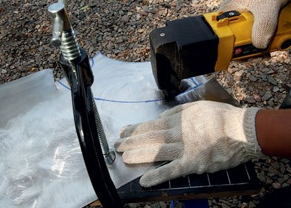
When working with electric scissors, the main enemy is vibration. Therefore, the workpiece must be securely fixed with a clamp. If necessary, you can very carefully dampen the vibrations by hand.

Fixed diameter pipes are easily molded around the pipe. This is mainly done by hand due to the effect of the lever, and the edges of the workpiece are rounded with a mallet. It is better to form the edges so that when joined they form a plane - it is easier to lay the weld.
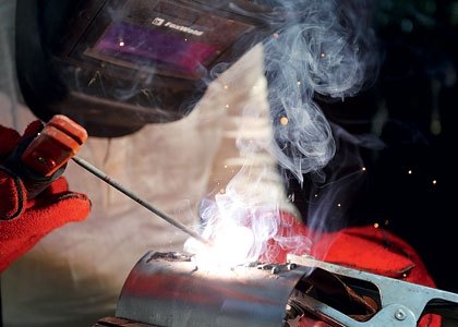
Welding thin sheet metal is a delicate job, especially if you use manual arc welding like we do. Perhaps, welding with a non-consumable tungsten electrode in an argon environment is better suited for this task, but the equipment for it is rare and requires specific skills.
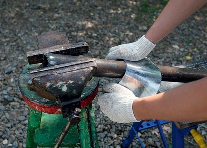
The bending of the conical sections is entirely manual labor. The key to success is to crimp the narrow end of the cone around the small diameter pipe, giving it more load than the wide end.
The valveless PUVRD is an amazing design. It has no moving parts, compressor, turbine, valves. The simplest PUVRD can even do without an ignition system. This engine can run on just about anything: replace a propane tank with a can of gasoline and it will continue to pulsate and produce thrust.
Unfortunately, HPJEs have failed in aviation, but recently they have been seriously considered as a source of heat in the production of biofuels. And in this case, the engine runs on graphite dust, that is, on solid fuel. Finally, the elementary principle of operation of a pulsating engine makes it relatively indifferent to manufacturing precision. Therefore, the manufacture of PuVRD has become a favorite pastime for people who are not indifferent to technical hobbies, including aircraft modelers and novice welders.
Despite all the simplicity, PuVRD is still a jet engine. It is very difficult to assemble it in a home workshop, and there are many nuances and pitfalls in this process. Therefore, we decided to make our master class multi-part: in this article we will talk about the principles of operation of the PuVRD and tell you how to make an engine case. The material in the next issue will be devoted to the ignition system and the starting procedure. Finally, in one of the following issues, we will definitely install our motor on a self-propelled chassis to demonstrate that it is really capable of creating serious traction.
From the Russian idea to the German rocket
It is especially pleasant to assemble a pulsating jet engine, knowing that for the first time the principle of operation of the PuVRD was patented Russian inventor Nikolai Teleshov back in 1864. The authorship of the first operating engine is also attributed to a Russian - Vladimir Karavodin. The famous V-1 cruise missile, which was in service with the German army during World War II, is rightfully considered the highest point in the development of the PuVRD.
Of course, we are talking about valve pulsating engines, the principle of operation of which is clear from the figure. The valve at the inlet to the combustion chamber freely passes air into it. Fuel is supplied to the chamber, a combustible mixture is formed. When the spark plug ignites the mixture, the excess pressure in the combustion chamber closes the valve. The expanding gases are directed into the nozzle, creating jet thrust. The movement of combustion products creates a technical vacuum in the chamber, due to which the valve opens and air is sucked into the chamber.
Are aircraft engines loud when landing?
For this purpose, the landing gear and aircraft design have been developed. This is a subjective feeling. At the final approach of landing - the last 10 km - the landing flaps and landing gear were extended. Due to the constant descent, the engines run just above idle speed - so they are correspondingly quiet.
Once the aircraft has landed on the runway, the main speed brakes reduce speed and at the same time the pilots in the cockpit activate the thrust switch, which maintains the braking process by diverting some of the engine power forward and braking.
Unlike a turbojet engine, in a PUVRD the mixture does not burn continuously, but in a pulsed mode. This explains the characteristic low-frequency noise of pulsating motors, which makes them inapplicable in civil aviation. From the point of view of efficiency, PuVRDs also lose to TRDs: despite the impressive thrust-to-weight ratio (after all, PuVRDs have a minimum of parts), the compression ratio in them reaches 1.2:1 at most, so the fuel burns inefficiently.
Until a few years ago, engine power was greatly increased. The redirected air and high speed caused a lot of noise. Currently, the speed of the engines does not rise above idle. As a result, noise is significantly reduced. However, this quickly changed when the engineers themselves learned the trade and pushed development in their own directions. As a result of the split in the Cold War, various events took place that only met with the collapse of the Soviet Union.
By Western standards, this is a special engine for which there is no comparable. This is a kerosene oxygen engine that provides more than 750 tons of thrust. In space, these are worlds. With comparable fuel, they will provide 20% less speed, but in fact empty solid boosters are about 1.5 times heavier than the kerosene-powered first stage. Only hydrogen engines have the best specific impulse yet reduce thrust at a comparable cost and deal with extremely large volumes and extremely low temperatures of liquid hydrogen.
But PUVRDs are invaluable as a hobby: after all, they can do without valves at all. In principle, the design of such an engine is a combustion chamber with inlet and outlet pipes connected to it. The inlet pipe is much shorter than the outlet. The valve in such an engine is nothing but the front of chemical transformations.
Thus, in the West, this lack of efficiency in the first stage must be compensated by the use of more expensive hydrogen engines in the rest of the rocket. Their own kerosene engines were much more inefficient.
They also use exhaust gas from fuel pumps as fuel in the engine. To do this, you had to experiment a lot to keep the engine from destroying itself, and the trick is not easy to master. To do this, it is necessary to burn a large amount of oxygen with a small amount of kerosene, resulting in a hot, oxygen-rich gas. This drives the turbine which drives the fuel pumps. Pumps deliver liquid oxygen and kerosene to the combustion chamber and oxygen-enriched exhaust gas.
The combustible mixture in the PuVRD burns out at subsonic speed. Such combustion is called deflagration (in contrast to supersonic combustion - detonation). When the mixture ignites, combustible gases escape from both pipes. That is why both the inlet and outlet pipes are directed in the same direction and together participate in the creation of jet thrust. But due to the difference in lengths, at the moment when the pressure in the inlet pipe drops, exhaust gases are still moving along the outlet pipe. They create a vacuum in the combustion chamber, and air is drawn into it through the inlet pipe. Part of the gases from the outlet pipe is also sent to the combustion chamber under the action of rarefaction. They compress a new portion of the combustible mixture and set fire to it.
Kerosene-rich exhaust gas cannot be used as it clogs the thin fuel passages with soot. However, hot gas with lots of oxygen under high pressure is a nightmare for every metal. It is extremely corrosive, and until recently only the Russians managed to build such engines. There was no investor who wanted to pay for it.
The jet engine condenses and burns the air. Where does high traction come from?
Because Russia signed a contract with Russia in the late 1990s to supply such engines. It was during the sale of Russia during the Yeltsin era. At least since the Crimean crisis, you are now in a pinch mill. Engines on a modern passenger aircraft.
The valveless pulsating engine is unpretentious and stable. It does not require an ignition system to maintain operation. Due to rarefaction, it sucks in atmospheric air without requiring additional pressurization. If you build a motor on liquid fuel (for simplicity, we preferred propane gas), then the inlet pipe regularly performs the functions of a carburetor, spraying a mixture of gasoline and air into the combustion chamber. The only moment when an ignition system and forced boost is needed is at start-up.
Extended and open jet engine. In a jet engine, air is drawn in from the outside and compressed. Liquid fuel is injected inside and burns in the combustion chamber. The product of this combustion is strongly expanded and then ejected through the exhaust nozzle.
The volume required by the air after combustion is much greater than the volume of incoming air at the front. For air to leave the engine, it must be much faster than the air that is flowing. In traditionally used turbine air jets, the combustion product drives a turbine which is thus rotated.
Chinese design, Russian assembly
There are several common designs for pulse jet engines. In addition to the classic “U-shaped pipe”, which is very difficult to manufacture, there is often a “Chinese engine” with a conical combustion chamber, to which a small inlet pipe is welded at an angle, and a “Russian engine”, which resembles a car muffler in design.
The amount of air/fuel mixture burned and the exit rate determine the thrust that a jet engine can achieve. The thrust force is created by the physical principle of recoil in the opposite direction of the gas jet. Modern large passenger aircraft engines use a so-called "secondary airflow" in which cold air circulates around the real engine and is also accelerated.
Why do these engines require a turbine? With the turbine driven by the combusted air/fuel mixture and set to rotate rapidly, the engine drives the compressor at the air inlet. There is also a large impeller in front of the compressor, which can be seen when looking at the engine from the front. This impeller is like a propeller, it sucks in large air masses and sends them to the compressor. The fan is also driven by a turbine.
Before experimenting with your own designs of PUVRD, it is highly recommended to build an engine according to ready-made drawings: after all, the sections and volumes of the combustion chamber, inlet and outlet pipes completely determine the frequency of resonant pulsations. If the proportions are not respected, the engine may not start. Various drawings of PUVRD are available on the Internet. We chose a model called "Giant Chinese Engine", the dimensions of which are given in the sidebar.
Again, fuel can be added and burned in the exhaust gases, which again increases the achievable thrust, but the fuel consumption also increases greatly. The afterburner is located behind the turbine. What fuel do the engines use? Modern jet engines use kerosene as fuel. This hydrocarbon blend, also referred to as air turbine fuel or jet fuel, is produced by refining petroleum.
And now the question is, what was this explosion? The explosion was caused by the loss of a compressor. Sometimes the airflow entering the engine is uneven or turbulent. In these cases, it is possible that some of the compressor blades, which after all are parts like the alar profile, are lost.
Amateur PUVRD are made of sheet metal. It is acceptable to use finished pipes in construction, but it is not recommended for several reasons. Firstly, it is almost impossible to select pipes of exactly the required diameter. It is all the more difficult to find the necessary conical sections.
Secondly, pipes, as a rule, have thick walls and an appropriate weight. For an engine that must have a good thrust-to-weight ratio, this is unacceptable. Finally, during operation, the engine is red-hot. If pipes and fittings made of different metals with different coefficients of expansion are used in the design, the motor will not last long.
So, we have chosen the path that most fans of PuVRD choose - to make a body from sheet metal. And immediately we faced a dilemma: turn to professionals with special equipment (CNC water-abrasive cutting machines, pipe rolls, special welding) or, armed with the simplest tools and the most common welding machine, go through the difficult path of a novice engine builder from start to finish. end. We preferred the second option.
Ingestion of an object such as a bird, a part separated from another apparatus, a block of ice, hail, etc. can damage the blades, change their shape and thus cause the loss of damaged blades. Typically, the damage is more extensive than in the first case, damaging an object with multiple blades. In this case, a chain reaction can occur, or rather the loss of the chain. When multiple blades become ineffective, those that follow in the compression sequence will be able to do the same.
If the air entering the engine is turbulent or insufficient, it can lead to loss of the compressor. For example, in the first video of this post. Hot, turbulent air blown back is sucked back into the engine, causing "compressor surge".
back to school
The first thing to do is to draw a sweep of future details. To do this, you need to remember school geometry and quite a bit of university drawing. Making reamers of cylindrical pipes is as easy as shelling pears - these are rectangles, one side of which is equal to the length of the pipe, and the second is the diameter multiplied by "pi". Calculating the development of a truncated cone or a truncated cylinder is a slightly more difficult task, for which we had to look into a drawing textbook.
Finally, we have a loss when the air that the engine sucks in is insufficient for normal operation. This is usually caused by an abnormal attitude of the aircraft. Excessive angle of attack, vertical climb in which you remain stationary in the air when you reach the top of the climb, etc.
At the beginning of the reactor age, this frequency was not uncommon. A sudden power change can become easier than it is now when the compressor comes on when the power plant needs more air. A good example was the Concorde, where as it took off, all the levers of power moved forward, although the engines took little time to accelerate.
The choice of metal is a very delicate issue. In terms of heat resistance, stainless steel is best for our purposes, but for the first time it is better to use black low-carbon steel: it is easier to form and weld. The minimum thickness of a sheet that can withstand the combustion temperature of the fuel is 0.6 mm. The thinner the steel, the easier it is to form and the more difficult it is to weld. We chose a sheet with a thickness of 1 mm and, it seems, made the right decision.
How is compressor loss detected?
As a rule, an increase in the temperature of the exhaust gases is perceived by the fuel that burns where it is absent. This will not be the case when the loss is complete, a situation in which a loud and disturbing "boom" will accompany the loss of engine power.
Depending on the severity of the compressor loss, an instantaneous power reduction is necessary to allow engine recovery; idling power adjustment or shutting down the engine completely to avoid more damage to this. In the event of a power outage due to the loss of a compressor, it will generally be possible to ignite it unless there is significant damage to the power plant.
Even if your welding machine can operate in plasma cutting mode, do not use it to cut reamers: the edges of parts treated in this way do not weld well. Hand shears for metal are also not the best choice, as they bend the edges of the workpieces. The ideal tool is electric scissors that cut millimetric sheet like clockwork.
Loss of a compressor in military exercises. Both engines stalled at 000 feet after losing a compressor, caused by speed too low for the altitude they were at. Raise both to a lower level and return to the hunt. Once it gets under your skin, you will never get it.
Obviously, before making the delivery of a motor engine, the manufacturer carries out a series of tests to ensure their quality. For testing, test benches are used, in which, if any motor does not meet the required characteristics or a malfunction, it is completely dismantled in search of failures. In test benches, the engine is subjected to normal operating conditions, which it must withstand.
To bend the sheet into a pipe, there is a special tool - rollers, or a sheet bender. It belongs to professional production equipment and therefore is unlikely to be found in your garage. A vise will help bend a decent pipe.
The process of welding mm metal with a full-size welding machine requires some experience. Slightly holding the electrode in one place, it is easy to burn a hole in the workpiece. When welding, air bubbles can get into the seam, which then leak. Therefore, it makes sense to grind the seam with a grinder to a minimum thickness so that the bubbles do not remain inside the seam, but become visible.
Sea level tests are performed under standard pressure and temperature conditions because gas turbine engines behave differently depending on environmental conditions. The motors are also tested under severe operating conditions such as water, sand, hail, etc. Simulation technology has advanced far enough to perform high-altitude tests, in which parameters are measured under flight conditions. In these tests, vacuum chambers are used to simulate pressure drop due to altitude.
The engine is subjected to changes in temperature, inlet pressure and load to control all the parameters that affect its operation. The materials that make up a turbojet engine are tested to the highest quality under operating conditions. These tests are done for materials based on their future work. Simulation is performed under the same mechanical and thermal conditions of the future work of the material.
In the next series
Unfortunately, within the framework of one article it is impossible to describe all the nuances of the work. It is generally accepted that these works require professional qualifications, but with due diligence they are all accessible to the amateur. We, journalists, were interested in learning new working specialties for ourselves, and for this we read textbooks, consulted with professionals and made mistakes.
We liked the case that we welded. It is pleasant to look at it, it is pleasant to hold it in hands. So we sincerely advise you to take up such a thing. In the next issue of the magazine, we will tell you how to make an ignition system and run a valveless pulse jet engine.


 Английский вокруг нас исследовательская работа")
