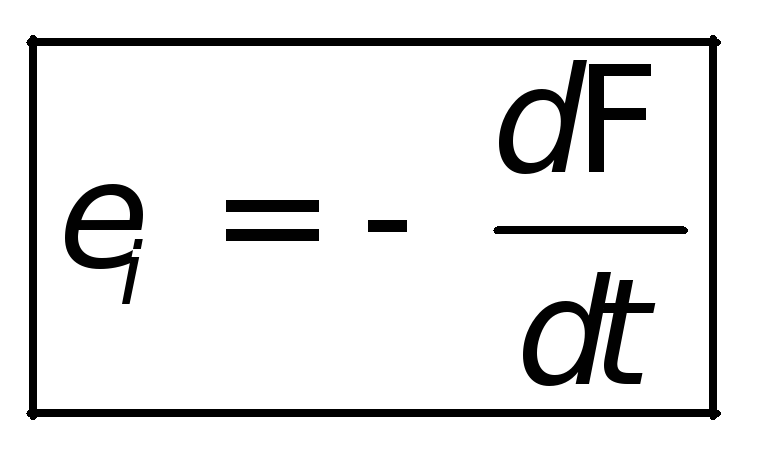
The law of electromagnetic induction is expressed by the formula. Law of electromagnetic induction (Faraday's law)
The most important law of electrical engineering is Ohm's law.
Joule-Lenz law
Joule-Lenz law
In verbal terms it sounds like this: The power of heat released per unit volume of the medium during flow electric current, is proportional to the product of the electric current density and the value electric field
where w- power of heat release per unit volume, - electric current density, - electric field strength, σ
- conductivity of the medium.
The law can also be formulated in integral form for the case of current flow in thin wires:
The amount of heat released per unit time in the considered section of the circuit is proportional to the product of the square of the current strength in this section and the resistance of the section
In mathematical form, this law has the form:
where dQ- the amount of heat released over a period of time dt,I- current strength, R- resistance, Q is the total amount of heat released during the time interval from t1 before t2.
In the case of constant current and resistance:
Kirchhoff's laws
Kirchhoff's laws (or Kirchhoff's rules) are the relationships that hold between currents and voltages in sections of any electrical circuit. Kirchhoff's rules allow you to calculate any electric circuits of direct and quasi-stationary current. They are of particular importance in electrical engineering because of their versatility, as they are suitable for solving any electrical problems. Applying Kirchhoff's rules to a chain allows one to obtain a system linear equations relative to currents, and accordingly, find the value of the currents on all branches of the circuit.
To formulate Kirchhoff's laws, nodes are distinguished in an electrical circuit - connection points of three or more conductors and contours - closed paths from conductors. In addition, each conductor can be included in several circuits.
In this case, the laws are formulated as follows.
First law(ZTK, Kirchhoff's Current Law) states that the algebraic sum of the currents in any node of any circuit is zero (the values of the outflowing currents are taken with the opposite sign):
In other words, how much current flows into the node, so much flows out of it. This law follows from the law of conservation of charge. If the chain contains p nodes, then it is described p − 1 current equations. This law may apply to other physical phenomena(for example, water pipes), where there is a law of conservation of magnitude and a flow of this magnitude.
Second Law(ZNK, Kirchhoff Voltage Law) states that the algebraic sum of voltage drops along any closed circuit circuit is equal to the algebraic sum of the EMF acting along the same circuit. If there is no EMF in the circuit, then the total voltage drop is zero:
for constant voltages: ![]()
for variable voltages:
In other words, when the circuit is bypassed along the contour, the potential, changing, returns to its original value. If the circuit contains branches, of which the branches contain current sources in the amount of , then it is described by the voltage equations. A special case of the second rule for a circuit consisting of one circuit is Ohm's law for this circuit.
Kirchhoff's laws are valid for linear and non-linear circuits for any nature of the change in time of currents and voltages.
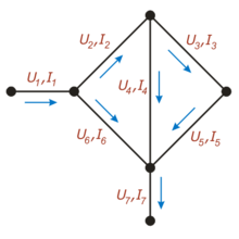
In this figure, for each conductor, the current flowing through it is indicated (the letter "I") and the voltage between the nodes connected by it (the letter "U")
For example, for the circuit shown in the figure, in accordance with the first law, the following relations hold:
Note that for each node, a positive direction must be chosen, for example here, currents flowing into the node are considered positive, and currents flowing out are considered negative.
In accordance with the second law, the following relations are valid:
If the current direction is the same as the loop bypass direction (which is arbitrarily chosen), the voltage drop is considered positive, otherwise it is negative.
Kirchhoff's laws, written for the nodes and contours of the chain, give complete system linear equations, which allows you to find all currents and voltages.
There is an opinion that "Kirchhoff's Laws" should be called "Kirchhoff's Rules", because they do not reflect the fundamental essence of nature (and are not a generalization of a large amount of experimental data), but can be derived from other provisions and assumptions.
FULL CURRENT LAW
FULL CURRENT LAW one of the fundamental laws electro magnetic field. Establishes the relationship between the magnetic force and the amount of current passing through the surface. The total current is understood as the algebraic sum of the currents penetrating the surface bounded by a closed loop.
The magnetizing force along the contour is equal to the total current passing through the surface bounded by this contour. In the general case, the field strength in different sections of the magnetic line can have different values, and then the magnetizing force will be equal to the sum of the magnetizing forces of each line.
Joule-Lenz law
Joule-Lenz law is a physical law that gives quantification thermal action electric current. Discovered in 1840 independently by James Joule and Emil Lenz.
In verbal terms it sounds like this:
The power of heat released per unit volume of the medium during the flow of an electric current is proportional to the product of the density of the electric current and the magnitude of the electric field
Mathematically it can be expressed in the following form:
where w- the power of heat release per unit volume, - the density of the electric current, - the strength of the electric field, σ - the conductivity of the medium.
LAW OF ELECTROMAGNETIC INDUCTION, Faraday's law is a law that establishes the relationship between magnetic and electrical phenomena. EMF of electromagnetic induction in the circuit is numerically equal and opposite in sign of the rate of change magnetic flux through the surface bounded by this contour. The magnitude of the EMF field depends on the rate of change of the magnetic flux.
FARADAY'S LAWS(named after the English physicist M. Faraday (1791-1867)) - the basic laws of electrolysis.
A relationship is established between the amount of electricity passing through the electrically conductive solution (electrolyte) and the amount of substance released at the electrodes.
When passed through an electrolyte direct current I within a second q = It, m = kIt.
FARADAY'S 2nd Law: The electrochemical equivalents of elements are directly proportional to their chemical equivalents.
gimlet rule
Gimlet Rule(also, the right hand rule) - a mnemonic rule for determining the direction of the angular velocity vector characterizing the rotational speed of the body, as well as the magnetic induction vector B or to determine the direction induction current.
Right hand rule
Right hand rule
gimlet rule: "If the direction forward movement gimlet (screw) coincides with the direction of the current in the conductor, then the direction of rotation of the gimlet handle coincides with the direction of the magnetic induction vector.
Determines the direction of the inductive current in a conductor moving in a magnetic field
Right hand rule: “If the palm of the right hand is positioned so that it includes lines of force magnetic field, and direct the bent thumb along the movement of the conductor, then four extended fingers will indicate the direction of the induction current.
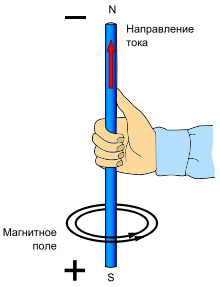
For solenoid it is formulated as follows: "If you grasp the solenoid with the palm of your right hand so that four fingers are directed along the current in the turns, then the thumb set aside will show the direction of the magnetic field lines inside the solenoid."

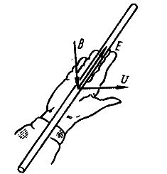
left hand rule
left hand rule
If a charge is moving and the magnet is at rest, then the left hand rule applies to determine the force: “If left hand position so that the lines of induction of the magnetic field enter the palm perpendicular to it, and four fingers are directed along the current (along the movement of a positively charged particle or against the movement of a negatively charged one), then the thumb set aside by 90 ° will show the direction operating force Lorentz or Ampère."
As a result of numerous experiments, Faraday established the basic quantitative law of electromagnetic induction. He showed that whenever there is a change in the flux of magnetic induction coupled to the circuit, an induction current appears in the circuit. The occurrence of an inductive current indicates the presence in the circuit electromotive force called electromotive force electromagnetic induction. Faraday found that the value of the EMF of electromagnetic induction E i is proportional to the rate of change of the magnetic flux:
E i \u003d -K, (27.1)
where K is the coefficient of proportionality, depending only on the choice of units of measurement.
In the SI system of units, the coefficient K = 1, i.e.
E i = - . (27.2)
This formula is Faraday's law of electromagnetic induction. The minus sign in this formula corresponds to the rule (law) of Lenz.
Faraday's law can also be formulated in this way: EMF of electromagnetic induction E i in the circuit is numerically equal and opposite in sign of the rate of change of the magnetic flux through the surface bounded by this circuit. This law is universal: EMF E i does not depend on how the magnetic flux changes.
The minus sign in (27.2) shows that an increase in flux (> 0) causes an EMF E i< 0, т.е. магнитный поток индукционного тока направлен навстречу потоку, вызвавшему его; уменьшение потока ( < 0) вызывает E i >0 i.e., the directions of the magnetic flux of the induction current and the flux that caused it are the same. The minus sign in formula (27.2) is the mathematical expression of Lenz's rule - general rule to find the direction of the induction current (and hence the sign and EMF induction), derived in 1833. Lenz's rule: the induction current is always directed in such a way as to counteract the cause that causes it. In other words, the induction current creates a magnetic flux that prevents a change in the magnetic flux that causes the induction EMF.
The induction emf is expressed in volts (V). Indeed, given that the unit of magnetic flux is weber (Wb), we get:
If the closed circuit in which the induction EMF is induced consists of N turns, then E i will be equal to the sum of the EMF induced in each of the turns. And if the magnetic flux covered by each turn is the same and equal to Ф, then the total flux through the surface of N turns is equal to (NF) - the total magnetic flux (flux linkage). In this case, the induction emf is equal to:
E i = -N× , (27.3)
 Formula (27.2) expresses the law of electromagnetic induction in a general form. It is applicable to both stationary circuits and moving conductors in a magnetic field. The time derivative of the magnetic flux included in it generally consists of two parts, one of which is due to the change in magnetic induction over time, and the other is due to the movement of the circuit relative to the magnetic field (or its deformation). Consider some examples of the application of this law.
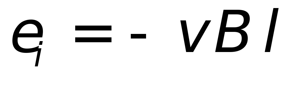
Example 1. A straight conductor of length l moves parallel to itself in a uniform magnetic field (Figure 38). This conductor may be part of a closed circuit, the remaining parts of which are motionless. Find the EMF that occurs in the conductor.
If the instantaneous value of the conductor's speed is v, then in time dt he will describe the area dS = l× v×dt and during this time will cross all the lines of magnetic induction passing through dS. Therefore, the change in the magnetic flux through the circuit, which includes a moving conductor, will be dФ = B n ×l× v×dt. Here B n is the magnetic induction component perpendicular to dS. Substituting this into formula (27.2) we obtain the value of the EMF:
E i = B n×l× v. (27.4)
The direction of the induction current and the sign of the EMF are determined by the Lenz rule: the induction current in the circuit always has such a direction that the magnetic field it creates prevents a change in the magnetic flux that caused this induction current. In some cases, it is possible to determine the direction of the induction current (the polarity of the induction EMF) according to another formulation of the Lenz rule: the induction current in a moving conductor is directed in such a way that the resulting Ampère force is opposite to the velocity vector (slows down the movement).
Let's take a numerical example. A vertical conductor (car antenna) with a length l = 2 m moves from east to west in the Earth's magnetic field with a speed v= 72 km/h = 20 m/s. Calculate the voltage between the ends of the conductor. Since the conductor is open, there will be no current in it and the voltage at the ends will be equal to the induction emf. Considering that the horizontal component of the magnetic induction of the Earth's field (i.e., the component perpendicular to the direction of movement) for mid-latitudes is 2 × 10 -5 T, according to formula (27.4) we find
U = B n×l× v\u003d 2 × 10 -5 × 2 × 20 \u003d 0.8 × 10 -3 V,
those. about 1 mV. The Earth's magnetic field is directed from south to north. Therefore, we find that the EMF is directed from top to bottom. This means that the lower end of the wire will have a higher potential (will be charged positively), and the upper end will be lower (will be charged negatively).
Example 2. There is a closed wire circuit in a magnetic field, penetrated by a magnetic flux F. Let us assume that this flux decreases to zero, and calculate the total amount of charge that has passed through the circuit. The instantaneous value of the EMF in the process of the disappearance of the magnetic flux is expressed by the formula (27.2). Therefore, according to Ohm's law, the instantaneous value of the current strength is
where R is the impedance of the circuit.
The value of the passed charge is equal to
q = = - = . (27.6)
The resulting relationship expresses the law of electromagnetic induction in the form found by Faraday, who concluded from his experiments that the amount of charge passed through the circuit is proportional to the total number of magnetic induction lines crossed by the conductor (i.e., the change in the magnetic flux Ф 1 -Ф 2), and is inversely proportional to the resistance of the circuit R. Relation (27.6) allows us to define the unit of magnetic flux in the SI system: weber is a magnetic flux, when it decreases to zero, a charge of 1 C passes in a circuit with a resistance of 1 Ohm linked to it.
According to Faraday's law, the occurrence of electromagnetic induction EMF is also possible in the case of a fixed circuit located in an alternating magnetic field. However, the Lorentz force does not act on stationary charges, therefore, in this case, it cannot be the cause of the induction EMF. Maxwell, to explain the EMF of induction in stationary conductors, suggested that any alternating magnetic field excites a vortex electric field in the surrounding space, which is the cause of the induction current in the conductor. The circulation of the intensity vector of this field along any fixed circuit L of the conductor is the EMF of electromagnetic induction:
E i = = - . (27.7)
The lines of intensity of the vortex electric field are closed curves, therefore, when a charge moves in a vortex electric field along a closed circuit, non-zero work is performed. This is the difference between the vortex electric field and the electrostatic field, the lines of intensity of which begin and end on the charges.
Fedun V.I. Abstract of lectures on the physics of Electromagnetism
Lecture 26
Electromagnetic induction. Faraday's discovery .
In 1831, M. Faraday made one of the most important fundamental discoveries in electrodynamics - he discovered the phenomenon electromagnetic induction .
In a closed conducting circuit, with a change in the magnetic flux (vector flux) covered by this circuit, an electric current arises.
This current is called induction .
The appearance of an induction current means that when the magnetic
|
|
flow in the circuit arises emf induction |
|
Figure 26.1. |
 . Changing the sign of the derivative
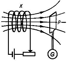
 Faraday discovered that an induction current can be induced in two different ways, which can be conveniently explained with a diagram.
1st method: moving the frame  in the magnetic field of a fixed coil
  (see fig.26.1).
2nd method: changing the magnetic field  generated by the coil , due to its movement or due to a change in the strength of the current
  in it (or both). Frame while being immobile.
In both these cases, the galvanometer  will show the presence of induction current in the frame .
The direction of the induction current and, accordingly, the sign of the emf. induction  determined by the Lenz rule.
Lenz's rule.
The induction current is always directed in such a way as to counteract the cause that causes it. .
Lenz's rule expresses an important physical property - the desire of a system to counteract a change in its state. This property is called electromagnetic inertia .
The law of electromagnetic induction (Faraday's law).
Whatever the reason for the change in the magnetic flux covered by a closed conducting circuit, which occurs in the emf circuit. induction is defined by the formula
|
|
Nature of electromagnetic induction.
In order to clarify the physical causes that lead to the emergence of emf. Induction, we consider two cases successively.
1. The circuit moves in a constant magnetic field.
act force
The electromotive force generated by this field is called electromotive force induction
. In our case
|
|
 .
.Here the minus sign is put because the third-party field  directed against the positive loop bypass defined by the right screw rule. Work
  is the rate of increment of the area of the contour (increment of the area per unit time), therefore
|
|
 ,
,where  - increment of the magnetic flux through the circuit.
|
|
 .
.The result obtained can be generalized to the case of an arbitrary orientation of the magnetic field induction vector relative to the contour plane and on any contour moving (and/or deforming) in an arbitrary way in a constant inhomogeneous external magnetic field.
So, the excitation of emf. induction during the movement of the circuit in a constant magnetic field is explained by the action of the magnetic component of the Lorentz force, proportional to  , which occurs when the conductor is moved.
2. The circuit is at rest in an alternating magnetic field.
The experimentally observed occurrence of an inductive current indicates that in this case, external forces appear in the circuit, which are now associated with a time-varying magnetic field. What is their nature? The answer to this fundamental question was given by Maxwell.
Since the conductor is at rest, the speed of the ordered movement of electric charges  and hence the magnetic force proportional to
  , is also equal to zero and can no longer set the charges in motion. However, in addition to the magnetic force, only a force from the electric field equal to
  . Therefore, it remains to conclude that induced current due to electric field
  arising when the external magnetic field changes in time.
It is this electric field that is responsible for the appearance of the emf. induction in a fixed circuit. According to Maxwell, a time-varying magnetic field generates an electric field in the surrounding space. The occurrence of an electric field is not associated with the presence of a conductive circuit, which only makes it possible to detect the existence of this field by the appearance of an induction current in it.
arising when the external magnetic field changes in time.
It is this electric field that is responsible for the appearance of the emf. induction in a fixed circuit. According to Maxwell, a time-varying magnetic field generates an electric field in the surrounding space. The occurrence of an electric field is not associated with the presence of a conductive circuit, which only makes it possible to detect the existence of this field by the appearance of an induction current in it.
Wording law of electromagnetic induction , given by Maxwell, is one of the most important generalizations of electrodynamics.
Any change in the magnetic field in time excites an electric field in the surrounding space .
The mathematical formulation of the law of electromagnetic induction in the understanding of Maxwell has the form:
Tension vector circulation this field along any fixed closed contour  is defined by the expression
|
|
 ,
,where  - magnetic flux penetrating the circuit .
Used to indicate the rate of change of the magnetic flux, the sign of the partial derivative indicates that the circuit is stationary.
Vector flow through a surface bounded by a contour , is equal to  , so the expression for the law of electromagnetic induction can be rewritten as follows:
This is one of the equations of Maxwell's system of equations.
The fact that the circulation of the electric field excited by a time-varying magnetic field is non-zero means that the considered electric field not potential.It, like a magnetic field, is eddy.
In general, the electric field can be represented by the vector sum of the potential (the field of static electric charges, the circulation of which is zero) and the vortex (due to the time-varying magnetic field) electric fields.
At the basis of the phenomena we have considered, which explain the law of electromagnetic induction, there is no general principle that makes it possible to establish the commonality of their physical nature. Therefore, these phenomena should be considered as independent, and the law of electromagnetic induction - as a result of their joint action. All the more surprising is the fact that the emf. induction in the circuit is always equal to the rate of change of the magnetic flux through the circuit. In cases where the field also changes and the location or configuration of the circuit in a magnetic field, emf. induction should be calculated by the formula
The expression on the right side of this equality is the total derivative of the magnetic flux with respect to time: the first term is associated with the change in the magnetic field over time, the second with the movement of the circuit.
It can be said that in all cases the induction current is caused by the total Lorentz force
|
|
 .
.What part of the induction current is caused by the electric, and what part of the magnetic component of the Lorentz force depends on choice of reference system.
On the work of the Lorentz and Ampère forces.
From the very definition of work, it follows that the force acting in a magnetic field on an electric charge and perpendicular to its velocity cannot do work. However, when a current-carrying conductor moves, carrying charges along with it, the Ampere force still does work. Electric motors serve as a clear confirmation of this.
This contradiction disappears if we take into account that the movement of a conductor in a magnetic field is inevitably accompanied by the phenomenon of electromagnetic induction. Therefore, along with the Ampere force, work on electric charges also performs the electromotive force of induction arising in the conductor. That., full work The force of the magnetic field consists of the mechanical work due to the Ampère force and the work of the emf induced by the movement of the conductor. Both works are equal in absolute value and opposite in sign, so their sum is equal to zero. Indeed, the work of the ampere force during the elementary displacement of a current-carrying conductor in a magnetic field is equal to  , during the same time emf induction does work
|
|
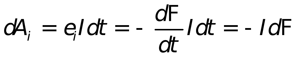 ,
,then full work  .
.
The Ampere forces do the work not due to the energy of the external magnetic field, which can remain constant, but due to the emf source that maintains the current in the circuit.


