magnetic induction at that point. A magnetic field. Magnetic field induction
How do two parallel conductors interact if the electric current flows in opposite directions?
Answer B
2. The Lorentz force is calculated by the formula:
Answer B
3. With an increase in magnetic induction by 3 times and a decrease in current strength by 3 times, the force acting on the conductor
Will not change because ∆F = BI∆L = 3B*1/3 IL = BIL
4. Ampere's force acts on a conductor with a current introduced into a magnetic field:
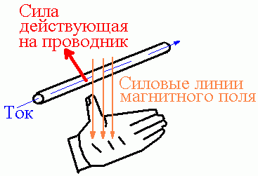
The direction of the Ampere force is determined by the following rule: if you direct the fingers of your left hand along the current so that the vector magnetic current entered the palm, then the thumb set aside will indicate the direction of Ampere's force.
Correct answer is D
5. Homogeneous induction magnetic field, which acts on a straight conductor 4 m long with a current of 4A, located at an angle of 30 degrees to the magnetic field lines with a force of 1N, is equal to
The force acting on a current-carrying conductor in a magnetic field is proportional to the current strength in the conductor I, magnetic induction B, conductor length L and the sine of the angle between the direction of the current in the conductor and the direction of the magnetic induction vector a (Ampère's Law):
F=B Lisina = 1H * 4 * 4 *sin 30° = 7.264
B \u003d F / (LIsina) \u003d 1 / (4 * 4 * 0.5) \u003d 0.1 T
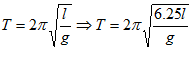
6. How will the frequency and period of oscillation of a mathematical pendulum change when the thread is increased by 6 ¼ times?
Mathematical pendulum - mechanical system, consisting of material point suspended on a weightless inextensible thread or on a weightless rod in a gravitational field. The period of small oscillations of a mathematical pendulum of length l in the gravitational field with acceleration free fall g is
 =2.5 times
T2 = 2π square root of (6.25l/g)
Т2/Т1 = 2.5 times
and does not depend on the amplitude and mass of the pendulum.
Answer: 2.5 times
7 .How will the period of oscillations in the oscillatory circuit change if the capacitance increases by 2 times, and the inductance of the coil decreases by 4 times?
Answer: the period of oscillation is t1 = 2π * (square root L1 * C1)
where t1 is the initial oscillation period;
L1 - initial inductance;
C1 - initial capacity;
The period of oscillation after changes in capacitance and inductance is t2 = 2π * (square root L2 * C2)
where t2 is the oscillation period after changes;
L2 = 4L1 - inductance after changes;
C2 = 2C1 - capacity after changes;
t2 \u003d 2π * (square root L2 * С2) \u003d 2π * (square root 1 / 4L1 * 2С1)
Let us determine the magnitude of the change in the oscillation period:
t2/t1 = 2π*(square root 4L1*2С1) / 2π*(square root L1*С1) =(square root 4L1*2С1) / (square root L1*С1)=
\u003d (square root 4 * 2) \u003d 2.8 times
8. The change in the charge of the capacitor in oscillatory show jumping occurs according to the law
What is the charge oscillation frequency?
25
9. The maximum charge on the capacitor plates of the capacitor of the oscillatory circuit q \u003d 10 -4 C. Determine the oscillation period in the circuit if Im=0.1A.
![]()
Im = wq = q/(square root of (L*C)
where Im is the current strength;
q is the maximum charge;
L is the inductance of the coil;
C is the capacitance of the capacitor
Hence w = Im/q
T = 2π/w = 2πq*10(power -4)/(0.1) = 0.0063

10. Why are oscillations in an oscillatory circuit called free?
An oscillatory circuit is an oscillatory system. This system has a state of stable equilibrium, characterized by a minimum of energy electric field(the capacitor is not charged). The system itself comes to this state, being taken out of it (capacitor discharge) and passes through it due to the phenomenon of self-induction. That is why free oscillations can exist in the circuit.
LOSS OF ELECTRIC ENERGY IN THE ELECTRICAL CIRCUIT CALCULATION OF SMOOTHING FILTERS OF TYPE LC CALCULATION OF A MULTIVIBRATOR ON OPERATIONAL AMPLIFIER IN STANDBY MODE
A change in the properties of space when permanent magnets are introduced into it can be interpreted as the presence of a material magnetic field in space, similar to electrostatic field around the still electric charges. Both electrostatic and magnetic fields are imperceptible by the human senses, but their presence can be registered using the simplest device - a light magnetic needle, mounted on an axle, i.e. using a compass.
AT early XIX in. it was found (H. Oersted) that the electric current flowing through the conductor also has an orienting effect on the compass needle (Fig. 5).
From Newton's third law it follows: with what force the conductor with electric current acts on the arrow, with the same force in absolute value and the arrow acts on the wire with current. Therefore, if we take a heavy magnet and a light coil with a large number of turns, then the coil with current begins to move relative to the magnet. The action of the school ammeter is based on this (see topic 17).
This discovery made it possible to establish a connection between electrical and magnetic phenomena and
build a unified picture called electromagnetic field theory.
At present, the idea that the action of permanent magnets is the cumulative action of molecular currents in matter (electrons moving in orbits in molecules) has finally been established.
A magnetic field can have a variety of effects on other physical objects that are in this field. The mechanical action that a magnetic field has on other bodies can be characterized by a force vector, and the field itself can be characterized by a vector physical quantity called magnetic induction, which allows you to determine this force. Magnetic induction is denoted by the letter , measured in teslas (T).
The module of the vector can be determined using the force acting on a moving free charge or current-carrying conductor, where the charges move along the conductor, as well as using the moment of forces acting on the frame through which the current flows.
We will assume that at a given point in space, the modulus of the magnetic induction vector is 1 Tesla (1 T), if at this point on a current-carrying conductor located perpendicular to the direction of the vector (with a different orientation, the force will be less), with a current strength of 1 A per unit length of the conductor (1 m), a force equal to 1 N acts.
The principle of superposition allows you to add the vectors of magnetic induction and magnetic fields created by different sources, according to the rules of vector addition.
The magnetic field induction can be determined at any point in space and at any time: .
Lines of magnetic induction
To visualize the picture of the change in the magnetic induction vector during the transition from one point of space to another, the concept is introduced magnetic induction vector lines (lines of force magnetic field). A continuous line, the tangent to which at any point defines the direction of the magnetic induction vector, is called magnetic field line. The density of field lines is directly proportional to the modulus of the magnetic induction vector.
Magnetic needles can be replaced with iron filings, which are magnetized in the field of this magnet and become small arrows. (Sawdust is poured onto the cardboard, which is placed on a magnet. When the cardboard is lightly shaken, the sawdust is well oriented.)
The field, at each point of which the magnetic induction vector is constant in magnitude and direction, is called homogeneous
The source of the magnetic field is not only permanent magnets, but also current-carrying conductors. A pattern of magnetic field lines created by a permanent horseshoe magnet ( a), a direct wire with current ( b) and a wire ring ( in), through which the current flows, is shown in Figure 9. The lines of force of the magnetic field are closed lines. In the outer space of permanent magnets, they go from the north pole to the south. The direction of the lines of force around a straight wire with current is determined by the gimlet rule (right-rotating screw, corkscrew): if the direction forward movement gimlet coincides with the direction of the current in the conductor, then the direction of rotation of the gimlet handle coincides with the direction of the magnetic induction vector.
25. The Biot-Savart-Laplace law is a physical law for determining the modulus of the magnetic induction vector at any point of the magnetic field generated by direct electric current in some area under consideration. It was established experimentally in 1820 by Biot and Savard. Laplace analyzed this expression and showed that with its help, by integrating, in particular, it is possible to calculate the magnetic field of a moving point charge, if we consider the movement of one charged particle as a current. Magnetic field strength. Current element. Law-Bio-Savart-Laplace. Calculation of the magnetic field strength of a circular coil with current on its axis. The magnetic field strength is the ratio mechanical force acting on the positive pole of the test magnet, to the value of its magnetic mass or the mechanical force acting on the positive pole of the test magnet of unit mass at a given point of the field. The tension is represented by the vector H having the direction of the mechanical force vector f.
Current element - a vector quantity equal to the product of the conduction current along line conductor and an infinitesimal segment of this conductor. Note. The current element has a direction coinciding with the direction of this segment. The Biot-Savart-Laplace law is a physical law for determining the induction vector of a magnetic field generated by a direct electric current. 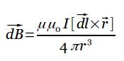  26.
26.
|
|
|
 Fig. 1 Examining the results of his numerous experiments, Faraday came to the conclusion that an induction current always occurs when a change in the flux of magnetic induction coupled to the circuit is carried out in the experiment. For example, when a closed conducting loop rotates in a uniform magnetic field, an induction current also appears in it - in this case, the magnetic field induction near the loop remains constant, and only the flux of magnetic induction through the loop changes. As a result of the experiment, it was also found that the value of the induction current is absolutely does not depend on the method of changing the flux of magnetic induction, but is determined only by the rate of its change(It is also proved in Faraday's experiments that the deviation of the galvanometer needle (current strength) is the greater, the greater the speed of the magnet, or the speed of change in the strength of the current, or the speed of the coils). The discovery of the phenomenon of electromagnetic induction was of great importance, since it was given the opportunity to obtain
 A current-carrying conductor in a magnetic field is subject to forces that are determined using Ampère's law. If the conductor is not fixed (for example, one of the sides of the circuit is made in the form of a movable jumper, Fig. 1), then under the action of the Ampere force it will move in the magnetic field. This means that the magnetic field does work to move the current-carrying conductor.
To calculate this work, consider a conductor of length l with a current I (it can move freely), which is placed in a uniform external magnetic field that is perpendicular to the plane of the circuit. The force, the direction of which is determined by the left hand rule, and the value - by the Ampère's law, is calculated by the formula
Under the action of this force, the conductor will move parallel to itself on the segment dx from position 1 to position 2. The work done by the magnetic field is equal to
Because l dx=dS - the area that the conductor crosses when it moves in a magnetic field, BdS=dФ - the flux of the magnetic induction vector that permeates this area. Means,
That is, the work of moving a current-carrying conductor in a magnetic field is equal to the product of the current strength and magnetic flux, crossed by a moving conductor. This formula is also valid for an arbitrary direction of the vector AT.
Calculate the work of moving a closed loop with direct current I in a magnetic field. We will assume that the circuit M moves in the plane of the drawing and, as a result of an infinitesimal displacement, will move to the position M "shown in Fig. 2 by a dashed line. The direction of the current in the circuit (clockwise) and the magnetic field (perpendicular to the plane of the drawing - beyond the drawing or from us) is given in Fig. We conditionally divide the circuit M into two conductors connected by their ends: ABC and CDA.
The work dA, which is performed by the Ampere forces during the investigated movement of the circuit in a magnetic field, is equal to the algebraic sum of the work on moving the conductors ABC (dA 1) and CDA (dA 2), i.e.
The forces that are applied to the CDA section of the contour form sharp corners with the direction of movement, so the work done by them dA 2 >0. .Using (1), we find that this work is equal to the product of the current strength I in our circuit and the magnetic flux crossed by the CDA conductor. The CDA conductor, during its movement, crosses the flow dФ 0 through the surface made in color, and the flow dФ 2, which penetrates the contour in its final position. Means,
The forces that act on the section ABC of the contour form obtuse angles with the direction of movement, which means that the work they do is dA 1<0. Проводник AВС пересекает при своем движении поток dФ 0 сквозь поверхность, выполненную в цвете, и поток dФ1, который пронизывает контур в начальном положении. Значит,
Substituting (3) and (4) into (2), we find an expression for elementary work:
Where dФ 2 -dФ 1 \u003d dФ "is the change in magnetic flux through the area, which is limited by the current circuit. Thus,
Integrating expression (5), we find the work that is done by the Ampere forces, with a finite arbitrary displacement of the contour in a magnetic field:
This means that the work of moving a closed loop with current in a magnetic field is equal to the product of the current strength in the loop and the change in the magnetic flux coupled to the loop. Expression (6) is true for a contour of any shape in an arbitrary magnetic field.
Lorentz force
If the electric field acts on both a moving and resting charge, then the magnetic field of a permanent magnet acts only on a moving charge.
The Lorentz force is the force acting in a magnetic field on an electric charge. q moving in space with speed . Its direction in the case when the charge positive and moves perpendicular to the magnetic induction vector, is determined by the left hand rule 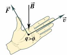
If the four fingers of the left hand (from the index to the little finger) are directed along the velocity vector, and the magnetic field lines enter the palm, then the thumb, 90 ° away from the other four fingers in the plane of the palm, shows the direction of the Lorentz force. All three vectors , , are mutually perpendicular.
If you want to determine the direction of the Lorentz force for a negative charge, then you must also use the left hand rule, and then change the direction of the resulting force by 180 °. Thus, with the same direction of charge velocities in a magnetic field, the Lorentz force will have mutually opposite directions for positive and negative charges. . It also depends on the angle a between the velocity vector
R = m/qB.
If a charge flies into a uniform magnetic field at an angle a to the vector, then its movement will occur along a helix.
Amp power

It has historically developed that the forces acting on a moving free electric charge, for example, an ion flying in a vacuum, and a charge moving in a direction in a conductor, an electric current, are separated. The nature of these forces is the same in both cases, however, in the case of an electric current in the conductor, the charge cannot leave the conductor, so we can talk about the force acting on the conductor as a whole.
The ampere force is the force acting on a current-carrying conductor placed in a magnetic field.
If a current-carrying conductor is l positioned above the palm of the left hand so that the magnetic induction vector was perpendicular to it and entered the palm, and positioned the four fingers of the hand in the direction of the current, then the bent thumb would indicate the direction of the Ampère force (Fig. 11). The direction of the Ampere force coincides with the direction of the Lorentz force, if we assume that positive particles move in the direction of current flow (see Fig. 11).
The module of the Ampere force is directly proportional to the current strength in the conductor, the module of the magnetic induction vector, the length of the conductor l and the sine of the angle a between the direction of the conductor and the direction of the vector :
F A \u003d IlB sin a
As can be seen from the formula, the force is maximum when a = 90°, i.e. the conductor is located perpendicular to the magnetic field lines.
If two parallel conductors are connected to a current source so that an electric current passes through them, then, depending on the direction of the current in them, the conductors either repel or attract.
The explanation of this phenomenon is possible from the standpoint of the appearance around the conductors of a special type of matter - a magnetic field.
The forces with which current-carrying conductors interact are called magnetic.
A magnetic field- this is a special kind of matter, a specific feature of which is the action on a moving electric charge, conductors with current, bodies with a magnetic moment, with a force depending on the charge velocity vector, the direction of the current strength in the conductor and on the direction of the magnetic moment of the body.
The history of magnetism goes back to ancient times, to the ancient civilizations of Asia Minor. It was on the territory of Asia Minor, in Magnesia, that a rock was found, samples of which were attracted to each other. According to the name of the area, such samples began to be called "magnets". Any magnet in the form of a rod or a horseshoe has two ends, which are called poles; it is in this place that its magnetic properties are most pronounced. If you hang a magnet on a string, one pole will always point north. The compass is based on this principle. The north-facing pole of a free-hanging magnet is called the magnet's north pole (N). The opposite pole is called the south pole (S).
Magnetic poles interact with each other: like poles repel, and unlike poles attract. Similarly, the concept of an electric field surrounding an electric charge introduces the concept of a magnetic field around a magnet.
In 1820, Oersted (1777-1851) discovered that a magnetic needle located next to an electrical conductor deviates when current flows through the conductor, that is, a magnetic field is created around the current-carrying conductor. If we take a frame with current, then the external magnetic field interacts with the magnetic field of the frame and has an orienting effect on it, i.e., there is a position of the frame at which the external magnetic field has a maximum rotating effect on it, and there is a position when the torque force is zero.
The magnetic field at any point can be characterized by the vector B, which is called magnetic induction vector or magnetic induction at the point.
Magnetic induction B is a vector physical quantity, which is a force characteristic of the magnetic field at a point. It is equal to the ratio of the maximum mechanical moment of forces acting on a loop with current placed in a uniform field to the product of the current in the loop and its area:
The direction of the magnetic induction vector B is taken to be the direction of the positive normal to the frame, which is related to the current in the frame by the rule of the right screw, with a mechanical moment equal to zero.
In the same way as the lines of electric field strength are depicted, the lines of magnetic field induction are depicted. The line of induction of the magnetic field is an imaginary line, the tangent to which coincides with the direction B at the point.
The directions of the magnetic field at a given point can also be defined as the direction that indicates
the north pole of the compass needle placed at that point. It is believed that the lines of magnetic field are directed from the north pole to the south.
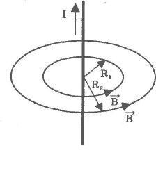
The direction of the lines of magnetic induction of the magnetic field created by an electric current that flows through a straight conductor is determined by the rule of a gimlet or a right screw. The direction of rotation of the screw head is taken as the direction of the lines of magnetic induction, which would ensure its translational movement in the direction of the electric current (Fig. 59).
![]()
where n 01 = 4 Pi 10 -7 V s / (A m). - magnetic constant, R - distance, I - current strength in the conductor.
Unlike electrostatic field lines, which start at a positive charge and end at a negative one, magnetic field lines are always closed. No magnetic charge similar to electric charge was found.
One tesla (1 T) is taken as a unit of induction - the induction of such a uniform magnetic field in which a maximum torque of 1 N m acts on a frame with an area of 1 m 2, through which a current of 1 A flows.
![]()
The induction of a magnetic field can also be determined by the force acting on a current-carrying conductor in a magnetic field.
A conductor with current placed in a magnetic field is subjected to the Ampère force, the value of which is determined by the following expression:
where I is the current strength in the conductor, l- the length of the conductor, B is the modulus of the magnetic induction vector, and is the angle between the vector and the direction of the current.
The direction of the Ampere force can be determined by the rule of the left hand: the palm of the left hand is positioned so that the lines of magnetic induction enter the palm, four fingers are placed in the direction of the current in the conductor, then the bent thumb shows the direction of the Ampere force.
Considering that I = q 0 nSv and substituting this expression into (3.21), we obtain F = q 0 nSh/B sin a. The number of particles (N) in a given volume of the conductor is N = nSl, then F = q 0 NvB sin a.
Let us determine the force acting from the side of the magnetic field on a separate charged particle moving in a magnetic field:
![]()
This force is called the Lorentz force (1853-1928). The direction of the Lorentz force can be determined by the rule of the left hand: the palm of the left hand is positioned so that the lines of magnetic induction enter the palm, four fingers show the direction of movement of the positive charge, the bent thumb shows the direction of the Lorentz force.
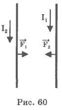
The force of interaction between two parallel conductors, through which currents I 1 and I 2 flow, is equal to:
where l- the part of a conductor that is in a magnetic field. If the currents are in the same direction, then the conductors are attracted (Fig. 60), if the opposite direction, they are repelled. The forces acting on each conductor are equal in magnitude, opposite in direction. Formula (3.22) is the main one for determining the unit of current strength 1 ampere (1 A).
The magnetic properties of a substance are characterized by a scalar physical quantity - magnetic permeability, showing how many times the induction B of a magnetic field in a substance that completely fills the field differs in absolute value from the induction B 0 of a magnetic field in vacuum:
According to their magnetic properties, all substances are divided into diamagnetic, paramagnetic and ferromagnetic.
Consider the nature of the magnetic properties of substances.
Electrons in the shell of atoms of matter move in different orbits. For simplicity, we consider these orbits to be circular, and each electron revolving around the atomic nucleus can be considered as a circular electric current. Each electron, like a circular current, creates a magnetic field, which we will call orbital. In addition, an electron in an atom has its own magnetic field, called the spin field.
If, when introduced into an external magnetic field with induction B 0, induction B is created inside the substance< В 0 , то такие вещества называются диамагнитными (n< 1).
AT diamagnetic In materials in the absence of an external magnetic field, the magnetic fields of electrons are compensated, and when they are introduced into a magnetic field, the induction of the magnetic field of an atom becomes directed against the external field. The diamagnet is pushed out of the external magnetic field.
At paramagnetic materials, the magnetic induction of electrons in atoms is not fully compensated, and the atom as a whole turns out to be like a small permanent magnet. Usually in matter all these small magnets are oriented arbitrarily, and the total magnetic induction of all their fields is equal to zero. If you place a paramagnet in an external magnetic field, then all small magnets - atoms will turn in the external magnetic field like compass needles and the magnetic field in the substance increases ( n >= 1).
ferromagnetic are materials that are n"1. So-called domains, macroscopic regions of spontaneous magnetization, are created in ferromagnetic materials.
In different domains, the induction of magnetic fields has different directions (Fig. 61) and in a large crystal
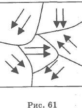
mutually compensate each other. When a ferromagnetic sample is introduced into an external magnetic field, the boundaries of individual domains are shifted so that the volume of domains oriented along the external field increases.
With an increase in the induction of the external field B 0, the magnetic induction of the magnetized substance increases. For some values of B 0, the induction stops its sharp growth. This phenomenon is called magnetic saturation.
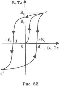
A characteristic feature of ferromagnetic materials is the phenomenon of hysteresis, which consists in the ambiguous dependence of the induction in the material on the induction of the external magnetic field as it changes.
The magnetic hysteresis loop is a closed curve (cdc`d`c), expressing the dependence of the induction in the material on the amplitude of the induction of the external field with a periodic rather slow change in the latter (Fig. 62).
The hysteresis loop is characterized by the following values B s , B r , B c . B s - the maximum value of the induction of the material at B 0s ; B r - residual induction, equal to the value of the induction in the material when the induction of the external magnetic field decreases from B 0s to zero; -B c and B c - coercive force - a value equal to the induction of the external magnetic field necessary to change the induction in the material from residual to zero.
For each ferromagnet, there is such a temperature (Curie point (J. Curie, 1859-1906), above which the ferromagnet loses its ferromagnetic properties.
There are two ways to bring a magnetized ferromagnet into a demagnetized state: a) heat above the Curie point and cool; b) magnetize the material with an alternating magnetic field with a slowly decreasing amplitude.
Ferromagnets with low residual induction and coercive force are called soft magnetic. They find application in devices where a ferromagnet has to be frequently remagnetized (cores of transformers, generators, etc.).
Magnetically hard ferromagnets, which have a large coercive force, are used for the manufacture of permanent magnets.
Ampère's law establishes that a current-carrying conductor placed in a uniform magnetic field, the induction of which is B, is affected by a force proportional to the strength of the current and the induction of the magnetic field:
F=BI l sina (a is the angle between the direction of the current and the induction of the magnetic field). This Ampère's law formula turns out to be valid for a rectilinear conductor and a homogeneous field.
If the conductor has an arbitrary formula and the field is inhomogeneous, then Ampère's law takes the form:
dF = I*B*dlsina
Ampère's law in vector form:
The Ampère force is directed perpendicular to the plane in which the vectors dl and B lie.
To determine the direction of the force acting on a current-carrying conductor placed in a magnetic field, it is used left hand rule.
Magní otheron ́ le - a force field acting on moving electric charges and on bodies with magnetic moment, regardless of the state of their movement , magnetic component electromagnetic field
The magnetic field can be created current of charged particles and/or magnetic moments electrons in atoms(and the magnetic moments of other particles, although to a much lesser extent) ( permanent magnets).
In addition, it appears in the presence of a time-varying electric field.
The main power characteristic of the magnetic field is magnetic induction vector
(magnetic field induction vector)
. From a mathematical point of view ![]() - vector field, defining and concretizing the physical concept of a magnetic field. Often the vector of magnetic induction is called simply a magnetic field for brevity (although this is probably not the most strict use of the term).
- vector field, defining and concretizing the physical concept of a magnetic field. Often the vector of magnetic induction is called simply a magnetic field for brevity (although this is probably not the most strict use of the term).
Another fundamental characteristic of the magnetic field (alternative magnetic induction and closely related to it, practically equal to it in physical value) is vector potential .
The magnetic field can be called a special kind of matter , through which interaction is carried out between moving charged particles or bodies that have magnetic moment.
Magnetic fields are necessary (in the context special relativity) is a consequence of the existence of electric fields.
Together, magnetic and electric fields form electromagnetic field, whose manifestations are, in particular, light and all others electromagnetic waves.
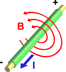
Electricity(I), passing through the conductor, creates a magnetic field (B) around the conductor.
From the point of view of quantum field theory, magnetic interaction - as a special case electromagnetic interaction carried by the fundamental massless boson - photon(a particle that can be represented as a quantum excitation of an electromagnetic field), often (for example, in all cases of static fields) - virtual.
|
[put away]
1 Magnetic field sources 2 calculation 3 Manifestation of a magnetic field 4 Mathematical representation 5 Magnetic field energy 6 Magnetic properties of substances 7 Currents Foucault 8 The history of the development of ideas about the magnetic field 9 See also 10 Notes |
For a quantitative description of the magnetic field, you can use the circuit with a current. Since the circuit with current experiences the orienting action of the field, a pair of forces acts on it in a magnetic field, which creates a moment of forces about some fixed axis. The torque of forces depends both on the properties of the field at a given point and on the properties of the contour. For a flat circuit with current I a value equal to the product of the current strength I To the square S bounded by a contour is called circuit magnetic moment p m .
The magnetic moment is a vector quantity. Its direction coincides with the direction of the positive normal to the contour.
\(~\vec p_m = IS \vec n,\)
where \(~\vec n\) is the unit vector of the normal to the contour plane.
Experience shows that the torque depends on the location of the circuit in a magnetic field. The torque is equal to 0 if the magnetic field is perpendicular to the contour plane (Fig. 2, a), and is maximum if the normal to the contour is perpendicular to the magnetic field (Fig. 2, b).
The maximum torque, as experience shows, is proportional to the strength of the current I and the area of the contour of the frame with current, i.e.
\(~M_(max) \sim IS .\)
If contours with different magnetic moments are placed at a given point of the magnetic field, then different torques will act on them, but the ratio \(~\frac(M_(max))(p_m)\) is the same for all contours and therefore can serve as a characteristic of the magnetic field, called magnetic induction.
Magnetic induction- this is a vector physical quantity, which is a force characteristic of the magnetic field, numerically equal to the maximum torque acting on the circuit with a unit magnetic moment, and directed along the positive normal to the circuit.
The modulus of magnetic induction is equal to
\(~B = \frac(M_(max))(IS) = \frac(M_(max))(p_m).\)
The SI unit of magnetic induction is the tesla (T).
1 T \u003d N m / (A m 2) \u003d N / (A m) .
1 T- magnetic induction of such a homogeneous field in which a torque of 1 Nm acts on a circuit with a magnetic moment of 1 A m 2.
Magnetic induction \(~\vec B\) completely characterizes the magnetic field. At each point, its modulus and direction can be found.
Field, at each point of which the magnitude and direction of magnetic induction are the same (\(~\vec B = \operatorname(const)\)) , called a uniform magnetic field.
If the magnetic field is generated by the system n conductors with currents, then, takes place principle of superposition of magnetic fields: the magnetic induction of the field of the system of currents is equal to the geometric sum of the magnetic induction of the fields of each of the currents separately:
\(~\vec B = \vec B_1 + \vec B_2 + \ldots + \vec B_n = \sum_(i=1)^n \vec B_i .\)
Literature
Aksenovich L. A. Physics in high school: Theory. Tasks. Tests: Proc. allowance for institutions providing general. environments, education / L. A. Aksenovich, N. N. Rakina, K. S. Farino; Ed. K. S. Farino. - Mn.: Adukatsy i vykhavanne, 2004. - C. 316-317.


