Power in the DC circuit, electrical energy and efficiency. D.C
One of the parameters characterizing the behavior of electrons in an electrical circuit, in addition to voltage and current, is power. It is a measure of the amount of work that can be done per unit of time. Work is usually compared to lifting weights. The greater the weight and height of its rise, the more work is done. Power determines how fast a unit of work can be done.
Units
The power of cars is calculated in horsepower - a unit of measurement invented by manufacturers of steam engines in order to measure the performance of their units in a conventional energy source of that time. The power of a car doesn't tell you how high it can go up a hill or how much weight it can carry, it only tells you how fast it can do it.
The power of the motor depends on its speed and the torque of the output shaft. Speed is measured in revolutions per minute. Torque is the torque of an engine, originally measured in lb-ft and now in newton meters or joules.
Tractor engine 100 hp. With. rotates slowly but with high torque. A motorcycle engine of equal power spins fast but with little torque. The power calculation equation has the form:
P = 2π S T / 33000, where S is the rotation speed, rpm, and T is the torque.
The variables here are torque and speed. In other words, power is directly proportional to ST: P~ST.
DC power
In electrical circuits, power is functionally dependent on voltage and current. Not surprisingly, it is similar to the P=IU equation above.
But here P is not proportional to the current multiplied by the voltage, but equal to it. It is measured in watts, abbreviated watts.
It is important to know that current and voltage do not determine power separately, only their combination. Voltage is work per unit of electric charge, and current is the speed of movement of charges. Stress (the equivalent of work) is like the work of lifting a weight against the force of gravity. Current (equivalent to speed) is like the speed of lifting a weight. Their product is the power.
Like tractor and motorcycle motors, a high voltage, low current circuit can be the same power as a low voltage, high current circuit. Voltage and current, out of relationship, cannot characterize the power of an electrical circuit.
An open circuit with voltage and zero current does no work, regardless of the height of the voltage. After all, according to the formula, anything multiplied by 0 gives 0: P \u003d 0 U \u003d 0. In a closed circuit of superconducting wire with zero resistance, you can achieve current at a voltage equal to zero, which also will not lead to energy dissipation: P \u003d I0 = 0.
Horsepower and watts mean the same thing: the amount of work that can be done per unit of time. These units are interconnected by the relation
1 l. With. = 745.7 W
Calculation example
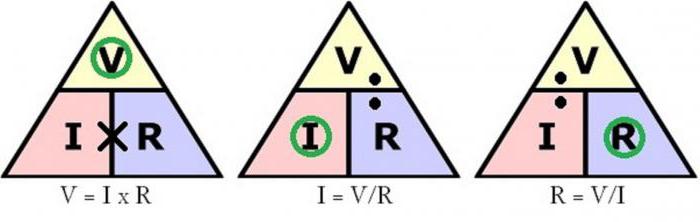
So, the current power of the electrical circuit in watts is equal to the product of voltage and current.
To determine, for example, the power of a load with a resistance of 3 ohms, in a circuit with a 12 V battery, it is necessary, by applying Ohm's law, to find the current
I \u003d U / R \u003d 12/3 \u003d 4 A
Multiplying the current strength by the voltage and will give the desired result:
P = I U = 4 A 12 V = 48 W
Thus, the lamp consumes 48 watts.
What happens when the voltage increases?
At a voltage of 24 V and a resistance of 3 ohms, the current
I=U/R=24/3=8A
When the voltage doubled, the current also doubled.
P=IU=8A 24V=192W
Power also increased, but more. Why? Because it is a function of the product of voltage and current, the voltage and current increased by 2 times, therefore, the power increased by 4 times. This can be checked by dividing 192 watts by 48, the quotient of which is 4.
Formula Options
By applying algebra to transform a formula, you can take the original equation and transform it for cases where one of the parameters is unknown.
Given voltage and resistance:
P \u003d (U / R) U or P \u003d U 2 / R
With a known current strength and resistance:
P = I (I R) or P = I 2 R
Historical fact: the relationship between power dissipation and current through resistance was discovered by James Prescott Joule, not Georg Simon Ohm. It was published in 1841 in the form of the equation P = I 2 R and is called the Joule-Lenz law.
Power equations:
- P = U I
- P = I 2 R
- P \u003d U 2 /R
Alternating current
Ohm's law and Joule-Lenz's have been established for direct current, but they are also valid for instantaneous values of varying current and voltage.
The instantaneous value of P is equal to the product of the instantaneous values of the current and voltage, taking into account their phase shift by the angle φ:
P(t) = U(t)I(t) = U m cosωt I m cos(ωt-φ) = (1/2)U m I m cosφ + (1/2) U m I m cos(2ωt- φ).
It follows from the equation that the instantaneous power has a constant component, and it performs oscillatory movements around the mean value with a frequency that is twice the frequency of the current.
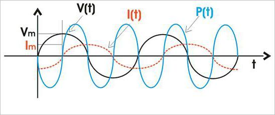
The average value of P(t), which is of practical interest, is:
P = (U m I m /2) cosφ
Taking into account the fact that cos φ=R/Z, where Z=(R 2 + (ωL - 1/ω C) 2) 1/2 and U m /Z = I m ,
Here I \u003d I m 2 -1/2 \u003d 0.707 I m is the effective value of the current strength, A.
Similarly, U \u003d U m 2 -1/2 \u003d 0.707 U m - effective voltage, V.
The average power through the effective voltage and current is determined by
P = U I cos φ, where cos φ is the power factor.
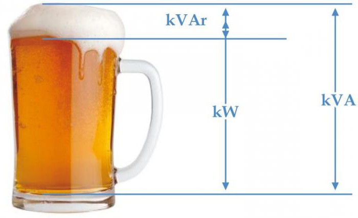
P in the electrical circuit is converted into heat or another form of energy. The highest active power can be achieved when cosφ=1, that is, in the absence of phase shift. It's called full power.
S \u003d U I \u003d Z I 2 \u003d U 2 / Z
Its dimension coincides with the dimension of P, but for the purpose of difference, S is measured in volt-amperes, VA.
The degree of intensity of energy exchange in the electrical circuit is characterized by reactive power
Q \u003d U I sinφ \u003d U I p \u003d U p I \u003d X I 2 \u003d U 2 / X
It has the dimensions of active and full, but for the purpose of distinguishing it, it is expressed in reactive volt-amperes, VAr.
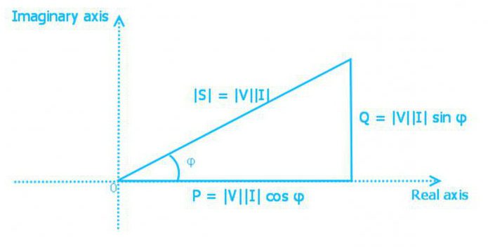
Power Triangle
Active, reactive and total power are interconnected by the expression
S = (P 2 + Q 2) 1/2
Power is represented as a side of a right triangle. Using the laws of trigonometry, one can find the length of one side (the amount of power of any type) from two known sides, or from the length of one and the angle. In such a triangle, active power is the adjacent leg, reactive power is the opposite side, and apparent power is the hypotenuse. The angle between the leg of the active power and the hypotenuse is equal to the phase angle of the impedance Z of the electrical circuit.
The complex form of this relationship is as follows:
S = P+jQ = U I cosφ + j U I sinφ= U I e jφ = U I*, where
S - complex power;
I* - complex conjugate current value.
The real component of the complex is active, and the imaginary component is reactive.
The instantaneous apparent power always remains constant.
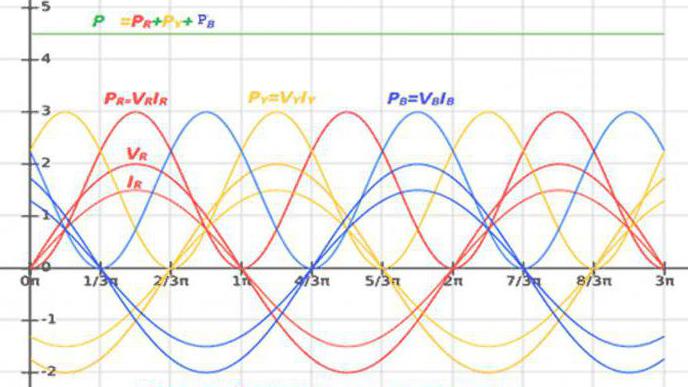
Three-phase current power
The load of each phase of a three-phase electrical circuit converts energy or exchanges it with a power source. As a result, P and Q of the circuit are equal to the total power of all phases:
P = P r + P y + P b ; Q \u003d Q r + Q y + Q b - star connection;
P = P ry + P yb + P br ; Q \u003d Q ry + Q yb + Q br - "triangle" connection.
The active and reactive powers of each phase are determined as in a single-phase circuit.
Total power of a three-phase circuit:
S \u003d (P 2 + Q 2) 1/2,
what in complex form has the form
S = P+jQ = (P r + P y + P b) + j(Q r + Q y + Q b)= S r + S y + S b = U r I r + U y I y + U b Ib
The symmetrical load of the phases results in the equality of their powers. That is why the current power is equal to three times the active and reactive power of the phase:
P = 3P f = 3 I f U f cosφ f = 3 R f I f 2
Q = 3 Q f = 3 I f U f sinφ f = 3 X f I f 2
S = 3 S f = 3 I f U f
I f and U f here you can replace them with linear values, given that for a star U f =U l; I f \u003d I l, and for a triangle U f \u003d U l; I f \u003d I l 3 -1/2:
P \u003d 3 1/2 I l U l cosφ f;
Q \u003d 3 1/2 I l U l sinφ f;
S = 3 1/2 I l U l.
Non-sinusoidal current
The definition of P in a non-sinusoidal current circuit is similar to its definition in a sinusoidal current circuit, since over the period T the average instantaneous power
P = 1/T∫u i dt
The active power of the current is determined by the sum P of the harmonic components, including the constant, which is the harmonic of zero frequency.
The reactive current power is similarly the result of adding the Q of each harmonic.
Q = ∑U k I k sinφ k = ∑ Q k
Crystal cell
Electricity. All metals are conductors electric current. They consist of a spatial crystal lattice, the nodes of which coincide with the centers positive ions. Free electrons move randomly around the ions.
In metals, electronic conductivity
Electric current in metals is called the ordered movement of free electrons.The direction of current is taken as the direction of movementpositively charged particles.
Electric charges can move in an orderly manner under the action of electric field, that's why condition for the existence of email. current is the presence of an electric field and free carriers of electric charge.
The current strength is numerically equal to the charge flowing through a given cross section of the conductor per unit time. The current is called constant, e If the current strength and direction does not change over time.
1 amp (A) equal to strength direct current, at which 1 C of electricity flows through any cross section of the conductor in 1 s. I = q 0 nvs The current in the circuit is measured. Circuit symbol
Work and current power. Electric current supplies us with energy. It arises due to the work of the electric field on the movement of free charges in the conductor. Consider the section of the circuit through which the current flows I. We denote the voltage in the section U, the resistance of the section is R. When current flows through a homogeneous section of the circuit, the electric field does work. During the time Δtcharge flows through the circuitΔ q = I Δ t . The electric field in the selected area does work.ΔA = U I Δ t — this work is calledwork of electric current . Due to the work in the area under consideration, mechanical work; may also leak chemical reactions. If this is not the case, then the work of the electric field only leads to heating of the conductor. The work of the current is equal to the amount of heat released by the current-carrying conductor:— Joule-Lenz law
The power of the electric current is equal to the ratio of the work of the current ΔA to the time interval Δ t for which this work was completed in this area: P = IU or . The work of an electric current in SI is expressed in joules (J), power - in watts (Tue).
Ohm's law for a closed circuit.
The current source has an EMF () and a resistance ( r
), which is called internal. Electromotive force (EMF) is the ratio of the work of external forces to move the charge q
along the chain, to the value of this charge ( 1V=1J/1C). Consider now a closed (complete) DC circuit, consisting of a source with electromotive force and internal resistance r
and an external homogeneous area with resistance R
. (R+r
) is the total resistance of the circuit. Ohm's law for complete chain is written in the form ![]() or
or
Electrical power P (W) is determined by the product of voltage and current strength:
where U is the voltage at the current collector, V; I - current through the current collector, A.
The unit of power is 1 watt \u003d 1 volt x 1 ampere. Taking into account Ohm's law (U \u003d IR; I \u003d U / R), equality (2.28) can be represented as follows:
P = U2/R. (2.30)
In practice, they use a derived unit of power - kilowatt (kW), 1 kW = 1000 watts. As in mechanics, electrical energy, or work (J), is equal to the product of power and time:
where P - power, W; t - time, s. The unit of energy is 1 joule = 1 watt x 1 second. In practice, a much larger unit is used - kilowatt-hour (kWh), 1 kWh \u003d 1 kW-1 h \u003d 1000 W-3600 s \u003d 3,600,000 J \u003d 3.6 MJ. If we take the value of P from expressions (2.28), (2.29) and (2.30), then formula (2.31) can be rewritten as follows:
W \u003d U It \u003d - t \u003d I 2 R t. (2.32)
Example 1 A heater connected to a 220 V network consumes a current of 5 A. How much energy is consumed per day? Solution. The amount of energy W = 220 ■ 5 24 = 26,400 Wh = 26.4 kWh = 95.04 MJ.
Example 2 What is the power of the heating device if the energy consumed in 5 hours is 10 kWh?
Solution. The power of the device P \u003d w / t \u003d 10/5 \u003d 2 kW. Thermal action current. The passage of an electric current through a conductor is accompanied by the release of heat. In heating appliances, obtaining heat is the ultimate goal. But in other devices and devices, heat generation is an unproductive loss. electrical energy. The amount of heat is measured in joules, with 1 J = 1 W-1 s = 1 W s.
According to the Lenz-Joule law, the amount of heat Q released by the current in the conductor is proportional to the square of the current, the resistance of the conductor and the time of passage of the current:
where I - current strength, A; R - resistance, Ohm; t - time, s.
Example 3 Find the amount of heat that is released on the resistance R = 20 Ohm for t = 1 h when the current / = 10 A flows. Solution. The desired amount of heat
Q = 100 ■ 20 ■ 3600 = 7200 kJ;
With every transformation of one type of energy into another, energy losses are observed. For example, when converting electrical energy into mechanical (in an electric motor), part of the electricity consumed by the electric motor from the network is spent on heating the motor, on friction in bearings, etc.
This process is quantitatively characterized by a value called the coefficient useful action(efficiency). The efficiency is understood as the ratio of the useful power R floor given by the machine to the input power P sub:
ή = P floor / P sub. . (2.34)
Example 4. A water heater consumes a power equal to 1 kW from the network, and 50 liters of water are heated by 80 ° C for 5 hours. water heater?
DC operation and power
The passage of electric current through the conductor is associated with the cost of a certain amount of energy. The measure of the amount of energy expended per unit of time is power:
P=A/t
where P - power; A is the amount of energy expended (work) during time t.
According to this formula, reduced to the form
A = Pt
you can calculate the energy consumption in order to determine the cost of operating electrical equipment.
Power in a DC electrical circuit is uniquely related to the resistance of this circuit and the current passing through it:
P \u003d I 2 R (3-12)
where I is current, R is resistance.
By making substitutions using Ohm's law, you can also get:
P=UI(3-12a)
and
P=U2/R(3-12b)
where U is the voltage at the ends of the circuit with resistance R.
If not all the power supplied (Рpodv) to the circuit is spent usefully in it (Рpol), then they talk about efficiency factor (COP) circuit, source, etc.
h = Рpol / Рsub
Because efficiency is always less than one, it is usually expressed as a percentage
Highly important issues are the modes of using current sources, in which maximum efficiency or the greatest "return".
Based on Ohm's law for the entire circuit, any real current source can be represented by an equivalent generator (Fig. 3-6, c), consisting of a series-connected generator E with zero internal resistance and a separate resistance Rin. By loading such a generator with resistance Rн, depending on the ratio of Rн and Rin, it is possible to obtain sharply different modes of operation of the current source.
If Rn >> Rvn, then the total resistance of the circuit is almost equal to the load resistance. In this case, a change in the value of Rn changes the current in the circuit, but has almost no effect on the voltage, which turns out to be very close to the value of the EMF all the time, i.e. Umax \u003d E
This mode of using the source is called the mode voltage generator. It is the main mode of operation of batteries and accumulators. In the voltage generator mode, the efficiency is very close to 100%, however, the power given to the external circuit is small, because small currents are taken from the source.
If we take small load resistance Rn< I max=E/Rin This mode is called the mode current generator. It is widely used in pentode amplifiers, which typically have many times the internal resistance of the load. In this case, the efficiency of the source is very low (a few percent or less), and the power taken from the source to the external circuit also turns out to be insignificant. Finally, the third mode, widely used in circuits with transistors, is negotiation mode, characterized by the equality of the load resistance to the internal resistance of the generator (Rl = Rvn). In this case, the voltage at the load is equal to half the EMF (U= 0.5 E), and the current is half the short-circuit current (I= 0.5 Imax); the power taken by the external circuit is maximum and equal to Rmax=E 2 /(4Rin) In this case, the efficiency of the source is 50%. The maximum power Pmax that the source is capable of delivering to the load in the matching mode is often also called the available power of the generator Pdisp.
An electric current passing through a conductor heats it. The greater the current and the smaller the cross-sectional area of the wire at a given current, the more the wire heats up. So that the heating of the devices by the current would not be very strong, the cross-sectional area of \u200b\u200bthe wires must be selected in accordance with the load current. The heating of the device largely depends on its design: the better the cooling conditions, the less the device will heat up.
When calculating wires, they use the current density that is permissible in different cases, that is, the permissible current value per 1 mm2 of the wire cross-sectional area. In the most common cases of radio repair practice, the following limiting values of current density y are guided:
1. For rheostats and ballast wire resistances made on porcelain or ceramic frames with one layer of bare wire, y = 6-10 a/mm2. For windings of electromagnets, relays, bells, designed for short-term switching on, y \u003d 4-5 a / mm2.
3. For windings of transformers with a power of up to 75 W, as well as for windings of chokes, relays and wire resistances with multilayer winding (for example, grid bias resistance), designed for long-term switching, y \u003d 2-3 A / mm2, the same power of 75- 300 W y= 1.5 A/mm2.
4. For shunts and additional resistances in measuring equipment y<1 а/ мм2.
5. For heating devices, depending on the wire material, device design and operating conditions, y = 8-20 a/mm2.
The determination of the wire diameter for a given current at an allowable current density, y, is carried out according to the formula:
where d is the required wire diameter, mm; - current, A; y is the current density, a/mm2.
When choosing non-wire resistances for radio equipment, they are guided by the power dissipated on the resistance during operation of the device. Non-wire resistors are available in various normally dissipated powers (0.25, 0.5, 1, 2 watts or more). When installing resistance in the apparatus, it is necessary to ensure that the power released in the resistance does not exceed the norm.
If there is no resistance at hand for the required load, then they resort to connecting several resistances, and in order not to complicate the calculations, it is recommended to connect the same resistances.
Wire resistances designed for a lower current than necessary are connected in parallel, and as many resistances must be connected as many times the current allowed for them is less than required. For example, if the current in the circuit is 0.3A, and we have at our disposal resistances designed for a current of 0.1A, then three such resistances must be connected in parallel to be included in the indicated circuit. But in order for their total resistance to be equal to the specified one, the value of each of the connected resistances must be three times less than the specified one. If 150 ohm resistance is required in the example shown, then each of the three connected resistances must have 450 ohm.
If, when winding wire resistances, there is no wire at hand for the required current load, then winding can be done with a thinner wire, but it can be carried out immediately in two or three wires. When winding in two wires, the diameter of the wires can be taken 1.4 times less than the norm, and when winding in three wires, 1.8 times.
Thermal effect of current
Electric power is spent on heating the resistance R. The amount of heat released over a period of time t is equal to the current work during this time:
Q=I2Rt
Magnetic action of current
The most important technical application of the magnetic action of current is the conversion of electric current energy into mechanical motion. Many electro-acoustic devices (loudspeakers, telephones), electrical measuring instruments, relays, etc. are built on this principle. An obligatory part of such devices is an electromagnet (a coil with a steel core) or a solenoid (a coil without a core). In some types of such devices, there are two coils. In addition, magnetic circuits, permanent magnets and special conductors for induced currents are used in electromagnetic devices.
From the formula for determining stress () it is easy to obtain an expression for calculating the work of transfer electric charge; since the current strength is related to the charge by the ratio, then the work of the current:, or.
Power by definition, therefore, .
Russian scientist X. Lenz and English scientists D. Joule empirically in the middle of the 19th century. independently established a law called Joule-Lenz law and reads like this: when current passes through a conductor, the amount of heat released in the conductor is directly proportional to the square of the current strength, the resistance of the conductor and the current passage time:
A complete closed circuit is an electrical circuit, which includes external resistances and a current source (Fig. 17). As one of the sections of the circuit, the current source has a resistance, which is called internal,.
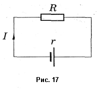
In order for the current to pass through a closed circuit, it is necessary that additional energy be imparted to the charges in the current source, it appears due to the work of moving charges, which is produced by forces of non-electric origin (external forces) against the forces of the electric field. The current source is characterized by an energy characteristic called EMF - source electromotive force. EMF is measured the ratio of the work of external forces to move along a closed circuit of a positive charge to the value of this charge.
Let an electric charge pass through the cross section of the conductor in time. Then the work of external forces when moving the charge can be written as follows: . According to the definition of current strength, , therefore . When this work is done on the inner and outer sections of the circuit, the resistances of which and , a certain amount of heat is released. According to the Joule-Lenz law, it is equal to: ![]() . According to the law of conservation of energy, . Consequently, . The product of the current and the resistance of a section of a circuit is often referred to as the voltage drop across that section. Thus, the EMF is equal to the sum of the voltage drops in the internal and external sections of a closed circuit. This expression is usually written like this:
. According to the law of conservation of energy, . Consequently, . The product of the current and the resistance of a section of a circuit is often referred to as the voltage drop across that section. Thus, the EMF is equal to the sum of the voltage drops in the internal and external sections of a closed circuit. This expression is usually written like this: ![]() . This dependence was experimentally obtained by Georg Ohm, it is called Ohm's law for a complete circuit and reads like this: the current strength in a complete circuit is directly proportional to the EMF of the current source and inversely proportional to the impedance of the circuit. In an open circuit, the EMF is equal to the voltage at the source terminals and therefore can be measured with a voltmeter.
. This dependence was experimentally obtained by Georg Ohm, it is called Ohm's law for a complete circuit and reads like this: the current strength in a complete circuit is directly proportional to the EMF of the current source and inversely proportional to the impedance of the circuit. In an open circuit, the EMF is equal to the voltage at the source terminals and therefore can be measured with a voltmeter.


