depends on the inductive current. So far, we have considered inductive currents in linear conductors. But induction currents will also arise in the thickness of solid conductors when the flux of the magnetic induction vector changes in them. Farah's experiments from a school physics course
Electrical and magnetic phenomena closely connected. And if the current generates magnetism, then the opposite phenomenon must also exist - the appearance of an electric current when the magnet moves. So reasoned the English scientist Michael Faraday, who in 1822 made the following entry in his laboratory diary: "Turn magnetism into electricity."
Since we are dealing with alternative fields, sinusoids must be stationary waves, so we will have, for example, phase 1: and 1 is the first harmonic or fundamental. As already mentioned, it is possible to approximate the rectangular fields generated by each stage through its fundamental.
Thus, the first harmonic or fundamental field is given. Which we know now. It should be noted that the maximum of the resulting time is from time to time in phase with the maximum of each of the bases in the sequence. Let us now turn to the 3-tone synonyms represented by functions.
This event was preceded by the discovery of the phenomenon of electromagnetism by the Danish physicist Hans Christian Oersted, who discovered the occurrence of a magnetic field around a current-carrying conductor. For many years, Faraday conducted various experiments, but the first experiments did not bring him luck. The main reason was that the scientist did not know that only an alternating magnetic field could create electricity. Real result was obtained only in 1831.
When the second index refers to the number or order of the harmonic, representing at the same time three, one immediately notices interesting fact: two of them are always in phase and in opposition to the rest, which means that their sum is always nothing. This is a fundamental and general rule.
Where is the speed of the magnetic field relative to the charge
The third harmonic spatial three-phase rotating field, as well as all multiple harmonics of the third, are zero. Only practical purposes retain meaning for the fifth and seventh harmonics. About 5 to Harmonica. Again, we can observe fluctuations of the three. As a result, they add
Faraday's experiments
Click on the picture
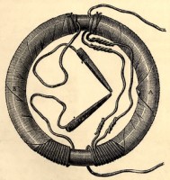
In an experiment carried out on August 29, 1931, the scientist wrapped coils of wires around the opposite sides of the iron ring. He connected one wire to a galvanometer. At the moment the second wire was connected to the battery, the galvanometer needle deviated sharply and returned to its original position. The same picture was observed when the contact with the battery was opened. This meant that an electric current appeared in the circuit. It arose as a result of lines of force the magnetic field created by the turns of the first wire crossed the turns of the second wire and generated a current in them.
The force with which this field acts on the charge
Then for the fifth harmonic it turned out. Using similar steps, one can demonstrate that, for example, the seventh harmonic progresses, the eleventh regression, etc. the order of the harmonics can be obtained from the formula. Now let's see what aspect of the field is described by the sum of the fundamental and 5 in the harmonic.
We compare this function with one and observe it. The approximation is pretty good: it describes with unwavering accuracy the deformation of the step field as it moves. This applies to all spatial harmonics. Spatial harmonics in a rotating field is a disturbance that you would avoid. The sinusoidal shape is closer to the number of pits and hence the distance between them. The spatial field harmonics cause iron losses in the rotor due to the frequency of the induced currents.
Faraday experience
A few weeks later, an experiment was carried out with a permanent magnet. Faraday connected a galvanometer to a coil of copper wire. Then, with a sharp movement, he pushed a cylindrical magnetic rod inside. At this moment, the galvanometer needle also swung sharply. When the rod was removed from the spool, the needle swung in the same way, but in the opposite direction. And this happened every time the magnet was pushed or pushed out of the coil. That is, the current appeared in the circuit when the magnet moved in it. So Faraday managed to "turn magnetism into electricity."
The value of E.D.S. induction
The frequency of the currents induced from the 5th harmonic is equal. The frequency of the currents induced 5 to the spatial harmonic is 6 times greater than the fundamental one. The same result is obtained for the 7th harmonic. In particular, the deformation caused by harmonic 7 can sometimes cause the thrusting engine to move. We offer several keywords, even on English language, to conduct targeted searches using the search box below. "Rotational magnetic field", "Asynchronous motor", "Asynchronous motor", "Asynchronous motor", "Asynchronous motor", "Generator", "Generator", "Generator", Synchronous motor, harmonica, harmonica, progressive waves, progressive waves , stationary waves, constant waves, etc.

Faraday in the laboratory
The current in the coil also appears if, instead of a permanent magnet, another coil connected to a current source is moved inside it.
In all these cases happened change magnetic flux penetrating the circuit of the coil, which led to the appearance of an electric current in a closed circuit. This Navali phenomenon electromagnetic induction , and the current by induction current .
The stator is a static part of an electrical machine. The image of the stator was obtained using the application of Professor Mirsad Todorovac - Department of Electronic and information systems- University of Zagreb. An important aspect of the vector representation of sinusoids should be explained or recalled here. In physics, oscillations are preferably described by a cosine function. This means that the values attributed to "a particular physical meaning, which are somewhat measurable, are represented by the real part of the complex number.
It is known that a current in a closed circuit exists if it maintains a potential difference with the help of electromotive force(EMF). Therefore, when the magnetic flux in the circuit changes, such an EMF arises in it. It is called EMF induction .
Faraday's Law
![]()
In electrical engineering, a common use is to express sinusoidal quantities with a sinusoidal function, in which the "physical", "measured" values of the quantities in question are represented by the imaginary part of a complex number, and therefore by the rotation of a rotating vector on the prescribed. See also: Complex numbers and sinusoidal variables are sinusoidal on this site. The sum of the magnetic fields in the presence of magnetic circuits with ferromagnetic materials is delicate work, since magnetic saturation makes the system non-linear.
The overlap effects are strictly true if the system operates in the linear zone of the magnetic object. the thickness of the air between the stator and the rotor, necessary to keep the rotation of the latter small in order to reduce magnetizing currents and stray fluxes. maximum torque is then needed to reduce it as much as possible. Why don't you calculate the circuit using real field lines? In this case, we will get rather incorrect field values. It is associated with the development and refinement induction motor. The "Leblanc cage" is capable of damping the vibrations of the generator.
Michael Faraday
Value electromagnetic induction does not depend on why the magnetic flux changes - whether the magnetic field itself changes or the circuit moves in it. It depends on the rate of change of the magnetic flux penetrating the circuit.
where ε - EMF acting along the contour;
F W - magnetic flux.
This section of the site offers exercises on electromagnetism. The collection of exercises on electromagnetism proposed below is intended both for university students scientific faculties as well as for high school students and technical institutes. Before proceeding to the exercises on electromagnetism, we briefly introduce electromagnetic phenomena.
Electromagnetism exercises
Just as current flowing into a conductor creates a magnetic field around it, even a magnetic field can, under certain conditions, create an electric current. Below are the electromagnetism exercises, listed in ascending order of difficulty.
The value of the EMF of a coil in an alternating magnetic field is affected by the number of turns in it and the magnitude of the magnetic flux. Faraday's law in this case looks like this:
![]()
where N – number of turns;
Difficulty level is medium to low. A straight half-meter conductor moves within a magnetic field with a strength of 10-4 tons at a constant speed and perpendicular to the lines of the field strength. Calculate the speed of the conductor in the field and how much is the work of Lorentz on one conducting electron.
Knowing that the intensity of the magnetic field is 0.5 T, the current and voltage induced on the resistance are determined. The finger is positioned on an orthogonal plane to a magnetic field with a voltage of 10-2 T and is connected to a 10 Ohm resistance. What will be the value of the tension caused by its leaders?
F W – magnetic flux through one turn;
Ψ - flux linkage, or the total magnetic flux interlocking with all turns of the coil.
Ψ = N F i
F i is the flow passing through one turn.
What is the value of the power dissipated in the resistor? The solenoid has the following physical characteristics. What should be the ratio of the number of turns of the primary circuit and the number of secondary transformers if the charger is connected to the Italian internal network voltage of 220 V?
Does 220V lead to peak voltage or effective voltage? Difficulty level is medium to high. The finger is placed in free fall but moving at a constant speed. A magnetic field with an intensity of 0.5 T acts perpendicular to the plane.
Even a weak magnet can create a large induction current if the speed of movement of this magnet is high.
Since an induction current occurs in conductors when the magnetic flux penetrating them changes, it will also appear in a conductor that moves in a fixed magnetic field. The direction of the induction current in this case depends on the direction of movement of the conductor and is determined by the right hand rule: “ If you place the palm of your right hand in such a way that it includes the lines of force of the magnetic field, and the thumb bent by 90 0 would show the direction of movement of the conductor, then the extended 4 fingers will indicate the direction of the induced EMF and the direction of the current in the conductor».
Calculate the speed at which the finger falls. You can find it here. Polarity chemical bonds is one of their main features. Whether it is polar or not depends on the difference in the electronegativity of the connecting atoms. In organic molecules, additional polarization of chemical bonds and the formation of delocalized bonds are observed. The reason is the so-called electronic effects, which are respectively inductive and mesometric effects.
The inductive effect is the further polarization of chemical bonds by the action of atoms, atomic groups, or larger substitutes of different electronegativity than carbon atoms. A mesenchymal or more coupling effect is observed when the electron density of chemical bonds in molecules is depolarized by the action of substituents. The mesomeric effect can also be positive or negative.
Lenz's rule

Emil Khristianovich Lenz
The direction of the induction current is determined by the rule that applies in all cases when such a current occurs. This rule was formulated by a Russian physicist of Baltic origin Emil Khristianovich Lenz: " The induction current that occurs in a closed circuit has such a direction that the magnetic flux created by it counteracts the change in the magnetic flux that this current caused.
Substituents are either atomic groups that are associated with a hydrocarbon chain, replacing one or more hydrogen atoms in it. Depending on the direction in which the electron density is removed, the inductive effect can be positive or negative. When the substitute adds an electron density and the links are negatively polarized in the opposite direction, we say that a positive inductive effect is observed.
The strength of the inductive influence of substitutes depends on their electronegativity. The induction effect falls off rapidly along the hydrocarbon chain and is usually strongest near an atom or atomic group which invokes it. In addition, the inductive effect is additive in nature, which means that the inductive effects of unidirectional polarizing substituents are collected if they are in close proximity to each other. Conversely, if the polarization action of two adjacent substituents is opposite, their induction effects are subtracted.
It should be noted that such a conclusion was made by the scientist on the basis of the results of experiments. Lenz created a device consisting of a freely rotating aluminum plate, at one end of which a solid aluminum ring was fixed, and at the other - a notched ring.
If the magnet was brought closer to a solid ring, it would repel and begin to “run away”.
Types of substitutes according to their inductive effect
Depending on the degree and direction of the influence of induction, substituents in the molecules of organic compounds are divided into three types. The first type is hydrocarbon substituents containing only sigma bonds. They have a positive induction effect. It grows due to its additivity in the order in which the substituent contains the primary, secondary, tertiary, and quaternary carbon atom, respectively.
Inductive effect of hydrocarbon substituents. The second type - positive charge or a neutral substitute that causes a negative inductive effect. Their polarization is greater than the electrification of the corresponding atoms. Neutral substitutions containing complex bonds have a negative inductive effect.
Click on the picture
When the magnet moved away, the ring tried to catch up with it.
Click on the picture
Nothing like this was observed with a cut ring.
Lenz explained this by the fact that in the first case, the induction current creates a magnetic field, the lines of induction of which are directed opposite to the lines of induction of the external magnetic field. In the second case, the lines of induction of the magnetic field created by the induction current coincide in direction with the lines of induction of the field of the permanent magnet. In a cut ring, no induction current occurs, so it cannot interact with a magnet.
Conjunction effect - mesometric effect
The third kind of substituents are those that have negative charge or are neutral and cause a positive inductive effect. As a rule, these are atomic groups of an atomic group or electrophoretic metal and non-metal atoms. The mesometric effect can be associated both with the emergence of a delocalized connection, and with the further intervention of the existing one. One can observe the interaction between π-electrons and π-electrons, or between π-electrons and β-electrons of an indestructible electron pair of a neighboring atom.
According to Lenz's rule, with an increase in the external magnetic flux, the induction current will have such a direction that the magnetic field created by it will prevent such an increase. If the external magnetic flux decreases, then the magnetic field of the induction current will support it and prevent it from decreasing.
Electric current generator

The mesenchymal effect may occur with or without the occurrence electric charges. Classical examples of the absence of electric charges after π-interactions are butadiene and benzene compounds. In the first there was a linear delocalization and in the second a circular depolarization.
Mesometric effect by type of substituents
Different types of spatial orientation are possible for different molecules. Delocalization in the butadiene molecule. Mesometric effect in the benzene molecule without the formation of charges. A positive mesometric effect is exhibited by substituents that give electron density upon conjugation.
Alternator
Faraday's discovery of electromagnetic induction made it possible to use this phenomenon in practice.
What happens if you spin a reel of more turns of metal wire in a fixed magnetic field? The magnetic flux penetrating the circuit of the coil will constantly change. And in it there will be an EMF of electromagnetic induction. This means that such a design can generate an electric current. The operation of alternators is based on this principle.
The generator consists of 2 parts - a rotor and a stator. The rotor is a moving part. In low power generators, most often rotates permanent magnet. In powerful generators, an electromagnet is used instead of a permanent magnet. Rotating, the rotor creates a changing magnetic flux, which generates an electric induction current in the turns of the winding located in the grooves of the stationary part of the generator - the stator. The rotor is driven by a motor. It can be a steam engine, a water turbine, etc.
Transformer
This is perhaps the most common device in electrical engineering, designed to convert electric current and voltage. Transformers are used in radio engineering and electronics. Without them, it is impossible to transmit electricity over long distances.
The simplest transformer consists of two coils with a common metal core. Alternating current, applied to one of the coils, creates an alternating magnetic field in it, which is amplified by the core. The magnetic flux of this field, penetrating the turns of the second coil, creates an induction electric current in it. Since the magnitude of the EMF of induction depends on the number of turns, by changing their ratio in the coils, one can also change the magnitude of the current. This is very important, for example, when transmitting electricity over long distances. After all, during transportation, large losses occur due to the fact that the wires heat up. By reducing the current with the help of a transformer, these losses are reduced. But at the same time, the tension increases. At the final stage, using a step-down transformer, reduce the voltage and increase the current. Of course, such transformers are much more complicated.
It is impossible not to say that not only Faraday tried to create an induction current. Similar experiments were also carried out by the well-known American physicist Joseph Henry. And he managed to succeed almost simultaneously with Faraday. But Faraday got ahead of him by publishing a report about his discovery before Henry.
>>Physics grade 11 >> The direction of the induction current. Lenz's rule
§10 DIRECTION OF INDUCTION CURRENT. LENTZ RULE
By attaching a coil in which an induction current occurs to a galvanometer, one can find that the direction of this current depends on whether the magnet approaches the coil (for example, the north pole) or moves away from it (see Fig. 2.2, b).
emerging induction current of one direction or another somehow interacts with the magnet (attracts or repels it). A coil with a current passing through it is like a magnet with two poles - north and south. The direction of the induction current determines which end of the coil acts as the north pole (the lines of magnetic induction come out of it). Based on the law of conservation of energy, it is possible to predict in which cases the coil will attract the magnet, and in which cases it will repel it.
Interaction of induction current with a magnet. If the magnet is brought closer to the coil, then an induction current appears in it in such a direction that the magnet is necessarily repelled. To bring the magnet closer to the coil, positive work must be done. The coil becomes similar to a magnet, turned with the same pole to the magnet approaching it. Like-named poles repel each other.
When the magnet is removed, on the contrary, a current arises in the coil in such a direction that a force attracting the magnet appears.
What is the difference between the two experiments: the approach of the magnet to the coil and its removal? In the first case, the number of magnetic induction lines penetrating the turns of the coil, or, what is the same, the magnetic flux, increases (Fig. 2.5, a), and in the second case it decreases (Fig. 2.5, b). Moreover, in the first case, the lines of induction of the magnetic field created by the induction current that has arisen in the coil come out of the upper end of the coil, since the coil repels the magnet, and in the second case, on the contrary, they enter this end. These lines of magnetic induction are shown in black in Figure 2.5. In case a, the coil with current is similar to a magnet, the north pole of which is above, and in case b - below.
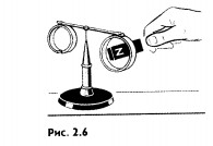
Similar conclusions can be drawn using the experience shown in Figure 2.6. At the ends of a rod that can freely rotate around vertical axis, two conductive aluminum rings are fixed. One of them has a cut. If you bring the magnet to the ring without a cut, then an induction current will appear in it and it will be directed in such a way that this ring will repel from the magnet and the rod will turn. If you remove the magnet from the ring, then it, on the contrary, will be attracted to the magnet. The magnet does not interact with the cut ring, since the cut prevents the induction current from occurring in the ring. The coil repels or attracts a magnet, it depends on the direction of the induction current in it. Therefore, the law of conservation of energy allows us to formulate a rule that determines the direction of the induction current.
Now we have come to the main point: with an increase in the magnetic flux through the coil turns, the induction current has such a direction that the magnetic field it creates prevents the magnetic flux from increasing through the coil turns. After all, the lines of induction of this field are directed against the lines of induction of the field, the change of which generates an electric current. If the magnetic flux through the coil weakens, then the induction
the current creates a magnetic field with induction, increasing the magnetic flux through the turns of the coil.
This is the essence general rule determining the direction of the inductive current, which is applicable in all cases. This rule was established by the Russian physicist E. X. Lenz.
According to Lenz's rule the inductive current arising in a closed circuit with its magnetic field counteracts the change in the magnetic flux by which it is caused. More briefly, this rule can be formulated as follows: the inductive current is directed so as to interfere with the cause that causes it.
Apply the Lenz rule to find the direction of the induction current in the circuit as follows:
1. Determine the direction of the lines of magnetic induction of the external magnetic field.
2. Find out whether the flux of the magnetic induction vector of this field through the surface bounded by the contour (Ф > 0) increases or decreases (Ф< 0).
3. Set the direction of the lines of magnetic induction of the magnetic field of the induction current. These lines should be, according to the Lenz rule, directed opposite to the lines of magnetic induction at Ф > 0 and have the same direction with them at Ф< 0.
4. Knowing the direction of the lines of magnetic induction, find the direction of the induction current using the gimlet rule.
The direction of the induction current is determined using the law of conservation of energy. In all cases, the induction current is directed so that its magnetic field prevents a change in the magnetic flux that causes this induction current.


