What is dielectric constant
The capacitance of a capacitor depends, as experience shows, not only on the size, shape and relative position of its constituent conductors, but also on the properties of the dielectric filling the space between these conductors. The influence of the dielectric can be established using the following experiment. We charge a flat capacitor and note the readings of an electrometer that measures the voltage across the capacitor. Let us then move an uncharged ebonite plate into the capacitor (Fig. 63). We will see that the potential difference between the plates will noticeably decrease. If you remove the ebonite, then the readings of the electrometer become the same. This shows that when air is replaced by ebonite, the capacitance of the capacitor increases. Taking some other dielectric instead of ebonite, we will get a similar result, but only the change in the capacitance of the capacitor will be different. If - the capacitance of the capacitor, between the plates of which there is a vacuum, and - the capacitance of the same capacitor, when the entire space between the plates is filled, without air gaps, with some kind of dielectric, then the capacitance will be times greater than the capacitance, where depends only on the nature of the dielectric. Thus, one can write
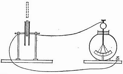
Rice. 63. The capacitance of a capacitor increases when an ebonite plate is pushed between its plates. The sheets of the electrometer fall off, although the charge remains the same
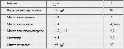
The value is called the relative dielectric constant or simply the dielectric constant of the medium that fills the space between the capacitor plates. In table. 1 shows the values of the permittivity of some substances.
Table 1. Dielectric constant of some substances
|
Substance |
|
|
Water (clean) |
|
|
Ceramics (radio engineering) |
|
The above is true not only for a flat capacitor, but also for a capacitor of any shape: by replacing air with some kind of dielectric, we increase the capacitance of the capacitor by a factor of 1.
Strictly speaking, the capacitance of a capacitor increases by a factor of only if all the field lines going from one plate to another pass through the given dielectric. This will be, for example, a capacitor that is completely immersed in some kind of liquid dielectric, poured into a large vessel. However, if the distance between the plates is small compared to their dimensions, then it can be considered that it is sufficient to fill only the space between the plates, since it is here that the electric field of the capacitor is practically concentrated. So, for a flat capacitor, it is enough to fill only the space between the plates with a dielectric.
By placing a substance with a high dielectric constant between the plates, the capacitance of the capacitor can be greatly increased. This is used in practice, and usually not air, but glass, paraffin, mica and other substances are chosen as a dielectric for a capacitor. On fig. 64 shows a technical capacitor, in which a paper tape impregnated with paraffin serves as a dielectric. Its facings are steel sheets pressed on both sides to waxed paper. The capacitance of such capacitors often reaches several microfarads. So, for example, an amateur radio capacitor the size of a matchbox has a capacitance of 2 microfarads.
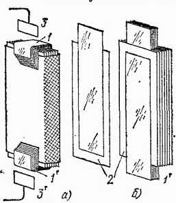
Rice. 64. Technical flat capacitor: a) assembled; b) in a partially disassembled form: 1 and 1 "- frame tapes, between which tapes of waxed thin paper 2 are laid. All tapes are folded together with an "accordion" and put into a metal box. Contacts 3 and 3" are soldered to the ends of tapes 1 and 1 " to include a capacitor in the circuit
It is clear that only dielectrics with very good insulating properties are suitable for the manufacture of a capacitor. Otherwise, the charges will flow through the dielectric. Therefore, water, despite its high dielectric constant, is not at all suitable for the manufacture of capacitors, because only extremely carefully purified water is a sufficiently good dielectric.
If the space between the plates of a flat capacitor is filled with a medium with dielectric constant, then formula (34.1) for a flat capacitor takes the form
The fact that the capacitance of a capacitor depends on the environment indicates that the electric field inside the dielectrics is changing. We have seen that when a capacitor is filled with a dielectric with a permittivity, the capacitance increases by a factor of . This means that with the same charges on the plates, the potential difference between them decreases by a factor. But the potential difference and the field strength are interconnected by the relation (30.1). Therefore, a decrease in the potential difference means that the field strength in the capacitor when it is filled with a dielectric becomes less by a factor. This is the reason for the increase in the capacitance of the capacitor.
If we denote by the strength of the field created by any charged bodies at a certain point in vacuum, and by the strength of the field at the same point in the case when, with the same charges, all space is filled with a dielectric with permittivity , then
If two point charges are in a dielectric, then the field strength of each of the charges at the point where the other charge is located also decreases by a factor and, therefore, the force acting on each of the charges is several times less than in vacuum. Hence we conclude that Coulomb's law (10.1) for point charges placed in a dielectric has the form
Any substance or body that surrounds us has certain electrical properties. This is due to the molecular and atomic structure: the presence of charged particles that are in a mutually bound or free state.
When no external electric field acts on the substance, these particles are distributed in such a way that they balance each other and do not create an additional electric field in the entire total volume. In the case of an external application electrical energy inside molecules and atoms, a redistribution of charges occurs, which leads to the creation of its own internal electric field directed opposite to the external one.
If the vector of the applied external field is designated "E0", and the internal - "E"", then the total field "E" will be the sum of the energy of these two quantities.
In electricity, it is customary to divide substances into:
conductors;
dielectrics.
Such a classification has existed for a long time, although it is rather conditional because many bodies have other or combined properties.
conductors
The media that have free charges act as conductors. Most often, metals act as conductors, because in their structure there are always free electrons that are able to move within the entire volume of the substance and, at the same time, are participants in thermal processes.
When the conductor is isolated from the action of external electric fields, then a balance of positive and negative charges from ionic lattices and free electrons. This equilibrium is immediately destroyed upon introduction - due to the energy of which the redistribution of charged particles begins and unbalanced charges of positive and negative values appear on the outer surface.
This phenomenon is called electrostatic induction. The charges arising from it on the surface of metals are called induction charges.
The inductive charges formed in the conductor form their own field E ", compensating the action of the external E0 inside the conductor. Therefore, the value of the total, total electrostatic field compensated and equal to 0. In this case, the potentials of all points both inside and outside are the same.

The conclusion obtained indicates that inside the conductor, even with an external field connected, there is no potential difference and no electrostatic fields. This fact is used in shielding - the application of a method of electrostatic protection of people and electrical equipment sensitive to induced fields, especially high-precision measuring instruments and microprocessor technology.

Shielded clothing and footwear made of fabrics with conductive threads, including headgear, is used in the power industry to protect personnel working in conditions of increased tension created by high-voltage equipment.
Dielectrics
So called substances with insulating properties. They contain only interconnected, not free charges. They have all positive and negative particles fastened inside a neutral atom, deprived of freedom of movement. They are distributed inside the dielectric and do not move under the action of the applied external field E0.
However, its energy still causes certain changes in the structure of the substance - inside the atoms and molecules the ratio of positive and negative particles changes, and on the surface of the substance there are excessive, unbalanced bound charges that form an internal electric field E ". It is directed counter applied from the outside tension.
This phenomenon has been named dielectric polarization. It is characterized by the fact that an electric field E appears inside the substance, formed by the action external energy E0, but weakened by the resistance of the internal E".
Types of polarization
It inside dielectrics is of two types:
1. orientation;
2. electronic.
The first type has the additional name of dipole polarization. It is inherent in dielectrics with displaced centers of negative and positive charges, which form molecules from microscopic dipoles - a neutral combination of two charges. This is typical for water, nitrogen dioxide, hydrogen sulfide.
Without the action of an external electric field in such substances, molecular dipoles are oriented in a chaotic manner under the influence of acting temperature processes. At the same time, there is no electric charge at any point of the internal volume and on the outer surface of the dielectric.
This pattern changes under the influence of externally applied energy, when the dipoles slightly change their orientation and regions of uncompensated macroscopic bound charges appear on the surface, forming a field E" with the opposite direction to the applied E0.

With such polarization, the processes are greatly influenced by temperature, which causes thermal motion and creates disorienting factors.
Electronic polarization, elastic mechanism
It manifests itself in non-polar dielectrics - materials of a different type with molecules devoid of a dipole moment, which, under the influence of an external field, are deformed in such a way that positive charges are oriented in the direction of the vector E0, and negative - in the opposite direction.
As a result, each of the molecules works as an electric dipole oriented along the axis of the applied field. They, in this way, create their own field E "with the opposite direction on the outer surface.

In such substances, the deformation of molecules, and, consequently, the polarization from the action of the field from the outside does not depend on their movement under the influence of temperature. An example of a non-polar dielectric is methane CH4.
The numerical value of the internal field of both types of dielectrics initially changes in magnitude in direct proportion to the increase in the external field, and then, when saturation is reached, nonlinear effects appear. They come when all the molecular dipoles are lined up along lines of force in polar dielectrics, or there have been changes in the structure of a non-polar substance due to a strong deformation of atoms and molecules from a large energy applied from outside.
In practice, such cases rarely occur - usually breakdown or insulation failure occurs earlier.
The dielectric constant
Among insulating materials, an important role is given to electrical characteristics and such an indicator as the dielectric constant . It can be assessed by two different characteristics:
1. absolute value;
2. relative value.
term absolute permittivity substances εa are used when referring to the mathematical notation of Coulomb's law. It, in the form of a coefficient εa, connects the vectors of induction D and intensity E.

Recall that the French physicist Charles de Coulomb used his own torsion balance to investigate the patterns of electric and magnetic forces between small charged bodies.
The determination of the relative permittivity of a medium is used to characterize the insulating properties of a substance. It evaluates the ratio of the strength of the interaction between two point charges under two different conditions: in vacuum and working environment. In this case, the vacuum indicators are taken as 1 (εv=1), while for real substances they are always higher, εr>1.
The numerical expression εr is displayed as a dimensionless quantity, is explained by the effect of polarization in dielectrics, and is used to evaluate their characteristics.
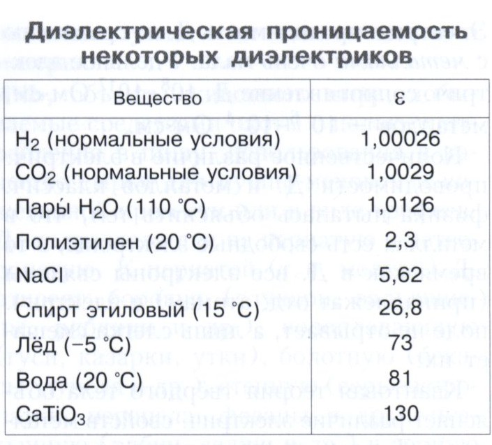
Dielectric constant values of individual media(at room temperature)
| Substance | ε | Substance | ε |
| Rochelle salt | 6000 | Diamond | 5,7 |
| Rutile (along the optical axis) | 170 | Water | 81 |
| Polyethylene | 2,3 | Ethanol | 26,8 |
| Silicon | 12,0 | Mica | 6 |
| Glass | 5-16 | Carbon dioxide | 1,00099 |
| NaCl | 5,26 | water vapor | 1,0126 |
| Benzene | 2,322 | Air (760 mmHg) | 1,00057 |
The interaction of currents - coming per unit length of each of each of the parallel conductors, is proportional to the magnitude of the currents and inversely proportional to the distance between them.
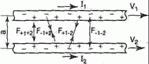
One important example of the magnetic interaction of currents is the interaction of parallel currents. The patterns of this phenomenon were experimentally established by Ampère. If two parallel conductors electric currents flow in the same direction, then there is a mutual attraction of the conductors. When currents flow in opposite directions, the conductors repel each other. The interaction of currents is caused by their magnetic fields: the magnetic field of one current acts by the force of Ampere on another current and vice versa.
In the formula we used:
The strength of the interaction of currents
Magnetic constant
Conductor length
Distance between two conductors
Dielectric constant - a value characterizing the dielectric properties of the medium - its response to an electric field.
In most dielectrics, at not very strong fields, the permittivity does not depend on the field E. In strong fields, however, electric fields(comparable to intra-atomic fields), and in some dielectrics in ordinary fields, the dependence of D on E is nonlinear
Same way the dielectric constant shows how many times the interaction force F between electric charges in a given medium, their interaction force Fo in vacuum is less
The relative permittivity of a substance can be determined by comparing the capacitance of a test capacitor with a given dielectric (Cx) and the capacitance of the same capacitor in vacuum (Co)
Table of permittivity values for solids
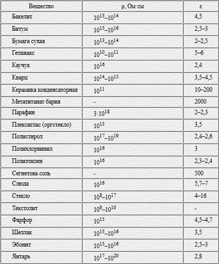
Table of dielectric values for liquids
Dielectric constant values table for gases 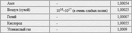
In the formula we used:
Electrical induction in the environment
Dielectric constant of the medium
Electric field strength
Force of interaction between charges in a medium
Force of interaction between charges in vacuum
The capacitance of the capacitor in the environment
Capacitor capacity in vacuum
Electric capacitance - a characteristic of a conductor (capacitor), a measure of its ability to accumulate an electric charge.
The capacitor consists of two conductors (plates), which are separated by a dielectric. The capacitance of the capacitor should not be affected by the surrounding bodies, so the conductors are shaped so that the field created by the accumulated charges is concentrated in a narrow gap between the capacitor plates. This condition is satisfied by: 1) two flat plates; 2) two concentric spheres; 3) two coaxial cylinders. Therefore, depending on the shape of the plates, capacitors are divided into flat, spherical and cylindrical.
Since the field is concentrated inside the capacitor, the lines of tension begin on one plate and end on the other, so the free charges that arise on different plates are equal in magnitude and opposite in sign. The capacitance of a capacitor is physical quantity, equal to the ratio of the charge Q accumulated in the capacitor to the potential difference (φ1 - φ2) between its plates
![]()
Page 1
The permittivity of vacuum is taken as unity. For most gases and vapors, it is close to unity, while for a number of other substances, the permittivity can be much greater than unity and reach several thousand.
The vacuum permittivity e0 is equal to 8 8542 X X10 - 14 f / cm, or 8 8542 - 10-14 C / V cm. If the bodies are immersed in a dielectric medium consisting of a polarizable substance, then the forces acting between the bodies in such a medium will be other than vacuum.
The permittivity of vacuum is denoted e0 and is called the electrical constant.
The vacuum permittivity eo is equal to 8 8542 X XO-14 F / cm, or 8 8542 10 - 14 C / V - cm. If the bodies are immersed in a dielectric medium consisting of a polarizable substance, then the forces acting between the bodies in such a medium will be other than vacuum.
EO - vacuum permittivity; c - dielectric permittivity of silicon; Na is the concentration of acceptor impurities in the base at the emitter junction; fk - contact potential difference, approximately equal to 1 V; U - reverse - voltage at the junction.
BO - vacuum permittivity; B, f - real and imaginary parts of the complex permittivity; 6 - dielectric loss angle.
An expression is found for the permittivity of vacuum in strong inhomogeneous fields, which is used to solve the problem of the distribution of a vacuum charge near a nucleus of an arbitrarily small radius. It turns out that, in addition to the polarization charge, which is taken into account by quantum electrodynamics, an important role is played by the charge of condensate electrons, which is lost in conventional calculations. Thus, electron condensation has a significant effect on the interaction of charged particles at short distances.
Since for the permittivity of vacuum ae, o 1, with identical particles in both systems, this similarity condition is satisfied if the charge possessed by the particles is proportional to the gas velocity.
The value of EL is called the vacuum permittivity.
Let us now see what the vacuum permittivity e0 is in the MKSA system. Let two charges ql qt k 3 - 109 COSE, separated by 1 m 0 asm from each other, interact in vacuum.
It should be noted that the vacuum permittivity value depends on the system of units.
In relation (8.7), eo denotes the permittivity of the vacuum, Ep is the electric field of the considered type of oscillations of the DR.
The ratio of the dielectric constant of a given material to the dielectric constant of vacuum is called the dielectric coefficient, which is an abstract value; it is sometimes called the permittivity.
Eo 8 85 - 10 - 3 - vacuum permittivity, pF / mm; e is the relative permittivity of the dielectric (c -), S is the area of the flat lining, mm2; b - distance between plates, mm. The nominal capacitance and its permissible deviations as a percentage are indicated on the capacitor case.
PM is the induced nonlinear polarization and e0 is the vacuum permittivity.
DIELECTRIC PERMEABILITY, the value of ε, characterizing the polarization of dielectrics under the action of an electric field of strength E. The dielectric constant is included in the Coulomb law as a quantity showing how many times the force of interaction of two free charges in a dielectric is less than in vacuum. The weakening of the interaction occurs due to the screening of free charges by the bound charges formed as a result of the polarization of the medium. Bound charges arise as a result of a microscopic spatial redistribution of charges (electrons, ions) in an electrically neutral medium as a whole.
The connection between the polarization vectors P, the electric field strength E and the electric induction D in an isotropic medium in the SI system of units has the form:
where ε 0 is an electrical constant. The value of the permittivity ε depends on the structure and chemical composition substances, as well as pressure, temperature and other external conditions(table).
For gases, its value is close to 1, for liquids and solids varies from several units to several tens, for ferroelectrics it can reach 10 4 . Such a spread in the values of ε is due to different polarization mechanisms that take place in different dielectrics.
The classical microscopic theory leads to an approximate expression for the permittivity of nonpolar dielectrics:
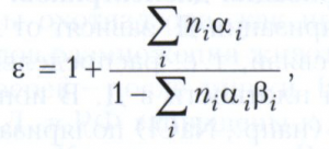
where n i is the concentration of the i-th kind of atoms, ions or molecules, α i is their polarizability, β i is the so-called internal field factor, due to the structural features of a crystal or substance. For most dielectrics with permittivity ranging from 2-8, β = 1/3. Usually, the permittivity is practically independent of the magnitude of the applied electric field up to the electrical breakdown of the dielectric. The high values of ε of some metal oxides and other compounds are due to the peculiarities of their structure, which allows, under the action of the field E, the collective displacement of the sublattices of positive and negative ions in opposite directions and the formation of significant bound charges at the crystal boundary.
The process of dielectric polarization when an electric field is applied does not develop instantly, but over a certain time τ (relaxation time). If the field E changes in time t according to a harmonic law with a frequency ω, then the polarization of the dielectric does not have time to follow it, and a phase difference δ appears between the oscillations P and E. When describing the oscillations P and E by the method of complex amplitudes, the permittivity is represented by a complex value:
ε = ε’ + iε",
moreover, ε' and ε" depend on ω and τ, and the ratio ε"/ε' = tg δ determines the dielectric losses in the medium. The phase shift δ depends on the ratio τ and the field period Т = 2π/ω. At τ<< Т (ω<< 1/τ, низкие частоты) направление Р изменяется практически одновременно с Е, т. е. δ → 0 (механизм поляризации «включён»). Соответствующее значение ε’ обозначают ε (0) . При τ >> T (high frequencies) the polarization does not keep up with the change in Ε, δ → π and ε' in this case denote ε (∞) (the polarization mechanism is “off”). Obviously, ε (0) > ε (∞) , and in variable fields the permittivity turns out to be a function of ω. Near ω = l/τ, ε' changes from ε (0) to ε (∞) (dispersion region), and the dependence tgδ(ω) passes through a maximum.
The nature of the dependences ε'(ω) and tgδ(ω) in the dispersion region is determined by the polarization mechanism. In the case of ionic and electronic polarizations with an elastic displacement of bound charges, the change in P(t) with a stepwise inclusion of the field E has the character of damped oscillations, and the dependences ε'(ω) and tgδ(ω) are called resonant. In the case of orientational polarization, the establishment of P(t) is exponential, and the dependences ε'(ω) and tgδ(ω) are called relaxation.
Methods for measuring dielectric polarization are based on interaction phenomena electromagnetic field with electric dipole moments of matter particles and are different for different frequencies. Most of the methods at ω ≤ 10 8 Hz are based on the process of charging and discharging a measuring capacitor filled with the investigated dielectric. At higher frequencies, waveguide, resonant, multifrequency and other methods are used.
In some dielectrics, for example, ferroelectrics, the proportional relationship between P and Ε [P = ε 0 (ε – 1)E] and, consequently, between D and E is violated even in ordinary electric fields achieved in practice. Formally, this is described as the dependence ε(Ε) ≠ const. In this case, important electrical characteristic dielectric is the differential permittivity:
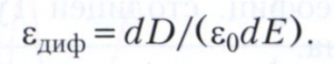
In nonlinear dielectrics, the value of ε diff is usually measured in weak alternating fields with the simultaneous imposition of a strong constant field, and the variable component ε diff is called the reversible permittivity.
Lit. see at st. Dielectrics.


