Rocket engines at home. How to make fuel for a homemade rocket
Piloting aircraft has become a hobby that unites adults and children from all over the world. But with the development of this entertainment, propellers for mini-planes are also developing. The most numerous engine for aircraft of this type is electric. But recently, jet engines (RD) have appeared on the arena of engines for RC aircraft models.
They are constantly supplemented with all sorts of innovations and notions of designers. The task before them is quite difficult, but possible. After the creation of one of the first models of a downsized engine, which became significant for aeromodelling, much changed in the 1990s. The first turbojet engine was 30 cm long, about 10 cm in diameter and weighing 1.8 kg, but over the decades, the designers managed to create a more compact model. If you thoroughly take up the consideration of their structure, then you can reduce the complexity and consider the option of creating your own masterpiece.
RD device
Turbojet engines (TRDs) operate by expanding heated gas. These are the most efficient engines for aviation, even carbon-fueled minis. From the moment the idea of creating an aircraft without a propeller appeared, the idea of a turbine began to develop throughout the society of engineers and designers. TRD consists of the following components:
- Diffuser;
- Turbine wheel;
- The combustion chamber;
- Compressor;
- stator;
- nozzle cone;
- guide apparatus;
- Bearings;
- Air intake nozzle;
- Fuel line and more.
Principle of operation
The structure of a turbocharged engine is based on a shaft that rotates with the help of compressor thrust and pumps air with rapid rotation, compressing it and directing it from the stator. Hitting more free space, the air immediately begins to expand, trying to find the usual pressure, but in the chamber internal combustion it is heated by the fuel, which causes it to expand even more.
The only way for the pressurized air to escape is to exit the impeller. With great speed, he strives for freedom, heading in the opposite direction from the compressor, to the impeller, which spins with a powerful stream, and begins to rotate rapidly, giving traction force to the entire engine. Part of the received energy begins to rotate the turbine, driving the compressor with more force, and the residual pressure is released through the engine nozzle with a powerful impulse directed to the tail section.
The more air is heated and compressed, the greater the pressure generated and the temperature inside the chambers. The resulting exhaust gases spin the impeller, rotate the shaft and enable the compressor to constantly receive fresh air flows.
Types of TRD control
There are three types of motor control:
Types of engines for aircraft models
Jet engines on model aircraft come in several basic types and two classes: air-jet and missile. Some of them are outdated, others are too expensive, but gambling lovers of controlled aircraft are trying to test the new engine in action. So average speed flying at 100 km / h, model aircraft are only becoming more interesting for the viewer and the pilot. The most popular types of engine differ for controlled and bench models, due to different efficiency, weight and thrust. There are few types in aeromodelling:
- Missile;
- Direct-flow air-jet (PRVD);
- Pulsating air-jet (PuRVD);
- Turbojet (TRD);
Missile used only on bench models, and then quite rarely. Its principle of operation is different from air-jet. The main parameter here is the specific impulse. Popular due to the lack of the need to interact with oxygen and the ability to work in zero gravity.
Direct flow burns the air out environment, which is sucked from the inlet diffuser into the combustion chamber. The air intake in this case sends oxygen to the engine, which, thanks to internal structure pressurizes the fresh air stream. During operation, air approaches the air intake at a flight speed, but in the inlet nozzle it sharply decreases several times. Due to the closed space, pressure is built up, which, when mixed with fuel, splashes out the exhaust from the back side at great speed.
Throbbing works identically to direct-flow, but in its case, the combustion of fuel is intermittent, but periodic. With the help of valves, fuel is supplied only at the necessary moments, when the pressure in the combustion chamber begins to drop. For the most part, a pulse jet engine performs between 180 and 270 fuel injection cycles per second. To stabilize the pressure condition (3.5 kg/cm2), forced air supply is used with the help of pumps.
turbojet engine, the device of which you considered above has the most modest fuel consumption, due to which they are valued. Their only downside is their low weight to thrust ratio. Turbine RD allow you to develop the speed of the model up to 350 km / h, while idling engine is kept at 35,000 rpm.
Specifications
An important parameter that makes model aircraft fly is thrust. It provides good power, capable of lifting large loads into the air. Thrust differs between old and new engines, but models built from 1960s blueprints, running on modern fuels, and upgraded with modern fixtures, efficiency and power increase significantly.
Depending on the type of taxiway, the characteristics, as well as the principle of operation, may differ, but all of them need to create optimal conditions for launch. The motors are started using a starter - other motors, mostly electric, which are attached to the motor shaft in front of the inlet diffuser, or the start is made by spinning the shaft with the help of compressed air supplied to the impeller.
engine GR-180
On the example of data from the technical passport of a serial turbojet engine GR-180 you can see the actual characteristics of the working model:
Thrust: 180N at 120,000 rpm, 10N at 25,000 rpm
RPM range: 25,000 - 120,000 rpm
Exhaust gas temperature: up to 750 C°
Jet blast velocity: 1658 km/h
Fuel consumption: 585ml/min (under load), 120ml/min (idle)
Weight: 1.2kg
Diameter: 107mm
length: 240mm
Usage
The main area of application has been and remains aviation orientation. Quantity and size different types Aircraft turbofan engines are staggering, but each one is different and used when needed. Even in aircraft models of radio-controlled aircraft From time to time, new turbojet systems appear, which are presented to the general public at exhibitions and competitions. Attention to its use allows you to significantly develop the capabilities of engines, supplementing the principle of operation with fresh ideas. In the last decade, skydivers and wingsuit extreme sport athletes have been integrating mini TRD as a source of thrust for flight using a wingsuit wingsuit fabric, in which case the motors are attached to the legs, or rigid wing, worn like a backpack on the back, to which the engines are attached.
Another promising direction use are combat military drones, on the this moment they are actively used in the US Army.
The most promising area for the use of mini turbojet engines is drones for transportation goods between cities and around the world.
Installation and connection
Installing a jet engine and connecting it to the system is a complex process. It is necessary to connect the fuel pump, bypass and control valves, tank and temperature sensors to a single circuit. Due to the impact high temperatures, refractory lined connections and fuel lines are commonly used. Everything is fixed with homemade fittings, a soldering iron and seals. Since the tubing may be as large as the head of a needle, the connection must be tight and insulated. Incorrect connection may result in destruction or explosion of the motor. The principle of connecting the chain on bench and flying models is different and must be carried out according to the working drawings.
Advantages and disadvantages of RD
Benefits for all types jet engines lots of. Each of the types of turbines is used for specific purposes, which are not afraid of its features. In aeromodelling, the use of a jet engine opens the door to overcoming high speeds and the ability to maneuver independently of many external stimuli. Unlike electric and internal combustion engines, jet models are more powerful and allow the aircraft to spend more time in the air.
conclusions
Jet engines for model aircraft can have different thrust, mass, structure and appearance. For aircraft modeling, they will always remain indispensable due to their high performance and the ability to use a turbine using different fuels and operating principles. By choosing certain goals, the designer can adjust the rated power, the principle of traction, etc., by applying different types turbines for different models. The operation of the engine on combustion of fuel and pressurization of oxygen makes it as efficient and economical as possible from 0.145 kg/l to 0.67 kg/l, which aircraft designers have always achieved.
What to do? Buy or DIY
This question is not simple. Since turbojet engines, whether they are full-scale or scaled-down models, they are technically complex devices. Making it out is not an easy task. On the other hand, mini turbojet engines are produced exclusively in the USA or European countries, which is why their average price is $ 3,000, plus or minus 100 bucks. So buying a ready-made turbojet engine will cost you $ 3,500, including shipping and all related pipes and systems. You can see the price yourself, just google “P180-RX turbojet engine”
Therefore, in modern realities, it is better to approach this matter as follows - what is called do-it-yourself. But this is not an entirely correct interpretation, rather give the work to contractors. The engine consists of mechanical and electronic parts. We buy components for the electronic part of the mover in China, we order the mechanical part from local turners, but for this you need drawings or 3D models and, in principle, the mechanical part is in your pocket.
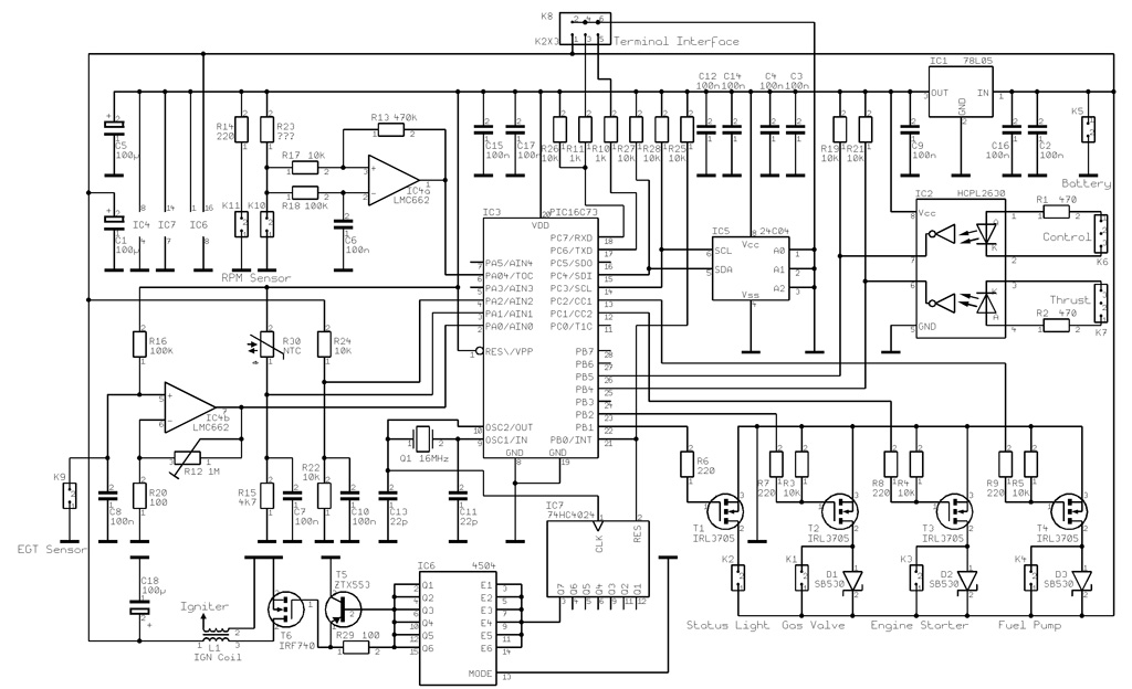
Electronic part
The controller for maintaining engine modes can be assembled on Arduino. To do this, you need a flashed Arduino chip, sensors - a speed sensor and a temperature sensor and actuators, an electronically controlled fuel supply damper. You can flash the chip yourself if you know programming languages, or go to the Arduino forum for a service.
Mechanical
With mechanics, all the spare parts in theory can be made by turners and millers, the problem is that for this you need to specifically look for them. It's not a problem to find a turner who will make the shaft and shaft sleeve, but everything else. The most difficult part to manufacture is the centrifugal compressor wheel. It is made either by casting. or on a 5-axis milling machine. The easiest way to get a centrifugal pump impeller is to buy it as a spare part for a car's internal combustion engine turbocharger. And already under it to orient all the other details.
Sometimes you want something weird. So, recently I was drawn to rocket modeling. Since I build rockets at the noob level, for me a rocket consists of two parts - an engine and a body. Yes, I know that everything is much more complicated, but even with this approach, rockets fly. Naturally, you are interested in how the engine is made.
I want to warn you that if you are going to repeat what is written in this article, you will do it at your own peril and risk. I do not guarantee the accuracy or safety of the proposed technique.
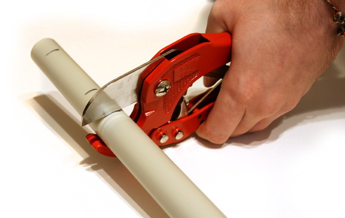
For the motor housing, I use 3/4" heavy wall PVC pipes. Pipes of this diameter are relatively cheap and widely available. Pipes are best cut with special scissors. I suffered a lot, trying to cut such pipes with an electric jigsaw - it always turned out very crooked.
I mark the pipe like this:
All dimensions are in inches. who does not know, the size in inches must be multiplied by 2.54 and you get the size in centimeters. These dimensions I found in a wonderful book
There are a bunch of other designs out there as well. The upper piece of the engine (which is empty) I do not. There should be an expelling charge for the parachute, I'm still far from that.
The cut piece of pipe is inserted into a special fixture. I will show all the adaptations at once, so that there are no questions:
A long stick plays the role of a “pestle.” Clay and fuel are compacted with it. The second detail is the conductor. It serves to drill a nozzle exactly in the center of the engine. Here are their drawings:
The drill is used long - 13 cm long. It is just enough to drill a channel through all the fuel.
Now you need to mix the fuel. I use the standard "caramel" - sugar and saltpeter in the ratio of 65 saltpeter / 35 sugar. I don’t want to melt caramel - this is a risky occupation, and it’s not worth that hemorrhoids. I'm not trying to get the best out of the fuel. It's amateur rocket science. I just mix powdered sugar and saltpeter in powders:

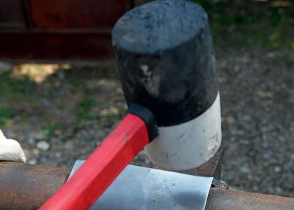
We hammer the powder according to the markup. You have to hit pretty hard.
Clogging fuel and plugs is no different. It seems that it is dangerous to knock on fuel, but caramel is difficult to ignite even from a match. Naturally, it is worth observing the basic precautions - do not bend over the engine, work in a protective mask, etc.
I leave the last 5mm plugs for hot melt adhesive. I tried several times to make a rocket without a hot melt plug, the top plug was torn out by pressure. Hot glue has excellent adhesion to plastic and does not have time to melt when the engine burns.
We drill the nozzle through the conductor:
Fuel is very poorly drilled - sugar melts and sticks to the drill, so it often has to be pulled out and the stuck fuel removed. Checking the nozzle:
We fill the last 5mm of the tube and its end with hot glue
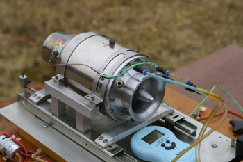
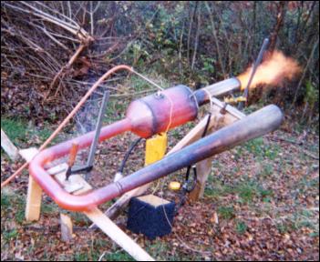
 Everything, the engine is ready. This is what the engine looks like on static tests. Unfortunately, the video is not indicative - in this engine, the channel was half-drilled, and the camera did not record the sound correctly. In real life, the “roar” of the engine is very loud and serious, and not as toy as on the record.
The valveless pulsating engine is the world's simplest jet engine. Its development was unfortunately put on hold with the start of widespread use of turbojet engines, but it continues to be of interest to amateurs, as it can be built in a home workshop. I built my motor by studying Lockwood's patent, according to which the device can be of any size, as long as certain proportions are observed. The engine has no moving parts, it can also run on any fuel if it is vaporized before entering the combustion chamber (I used a mixture of gasoline and diesel fuel in equal parts), but the start is on gas (this is much easier). The design is simple and relatively inexpensive to repeat. I do not know how often explosions occur in the combustion chamber of my engine, but I guess that this happens about 30-50 times per second, the operation of the device is accompanied by a very loud noise. I hope someday to measure this frequency.
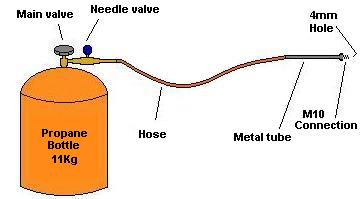
The engine runs on propane, which enters the combustion chamber through a long metal tube, at the end of which there is an atomizer that helps to vaporize the liquid fuel. When propane is used, a sprayer is not necessary, in my case the gas comes directly through a tube with an internal diameter of 4 mm. The tube is connected to the combustion chamber with a 10mm fitting. I have three of these tubes made - one for propane, the other two for diesel fuel and kerosene.
During the start process, propane is fed into the combustion chamber, and then just one spark on the candle is enough to start the engine.
According to the patent, it is possible to build such an engine of any size. My drawing shows my version of the device, which is slightly different from the design of the exhaust pipe proposed in the patent, which simplifies manufacture, however, since I did not measure thrust, this may have affected efficiency. Flow straighteners usually double the thrust, and I'm going to try making them.
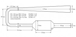 Drawing abbreviations:
- NL - nozzle length
- NM - nozzle diameter
- CL - Combustion chamber length
- CM - combustion chamber diameter
- TL - Tail pipe length
- TM - Tail pipe diameter
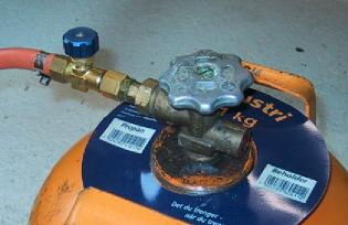
You can buy gas cylinders anywhere, I chose the 11 kg one with an industrial connector. I didn't use any reducers, I just installed a needle valve, since the gas flow is quite large and a regular reducer will not give the desired flow. The chance that the propane in the tube and tank will catch fire is very small if you do not empty the tank to the end. On the pictures below you can see what it looks like.
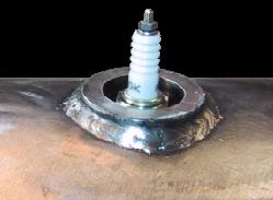
The spark plug is screwed into a part specially made on a lathe and welded into the combustion chamber. You can use any spark plug, I installed the NGK BP6E S without any additional resistance, and I used the bobbin from an old car. Also I did electronic circuit to get a spark, which you need to get only once, at the moment the engine starts.
The body of the pipe is welded from 3mm 316L stainless steel. I did not know how to calculate the thickness, and just took a thicker sheet, with a margin. The engine has been started many times and no problems have been found.
This entry was posted on Wednesday, January 23, 2008 at 5:11 pm. Rubric: News. You can subscribe to comments on this post. All pings are prohibited.
Did you know that if you put dry alcohol into a pipe bent by an arc, blow it with air from a compressor and supply gas from a cylinder, then it will go berserk, will yell louder than a taking off fighter and blush with anger? This is a figurative, but very close to the truth description of the operation of a valveless pulse jet engine - a real jet engine that anyone can build.
Schematic diagram Valveless PUVRD does not contain a single moving part. The front serves as a valve chemical transformations formed during the combustion of fuel.
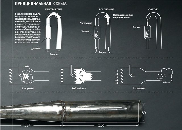
A mechanical valve helps the engine run more efficiently.

To make it pleasant and safe to work, we pre-clean the sheet metal from dust and rust with a grinder. The edges of sheets and parts are usually very sharp and full of burrs, so you need to work with metal only with gloves.
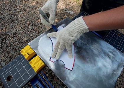
Before going to the workshop, we drew on paper and cut out templates for the parts in full size. It remains only to circle them with a permanent marker to get the markup for cutting.
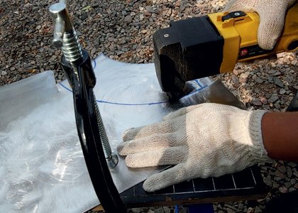
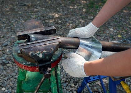
When working with electric scissors, the main enemy is vibration. Therefore, the workpiece must be securely fixed with a clamp. If necessary, you can very carefully dampen the vibrations by hand.
Fixed diameter pipes are easily molded around the pipe. This is mainly done by hand due to the effect of the lever, and the edges of the workpiece are rounded with a mallet. It is better to form the edges so that when joined they form a plane - it is easier to lay the weld.

Welding thin sheet metal is a delicate job, especially if you use manual arc welding like we do. Perhaps, welding with a non-consumable tungsten electrode in an argon environment is better suited for this task, but the equipment for it is rare and requires specific skills.
The bending of the conical sections is entirely manual labor. The key to success is to crimp the narrow end of the cone around the small diameter pipe, giving it more load than the wide end.
The valveless PUVRD is an amazing design. It has no moving parts, compressor, turbine, valves. The simplest PUVRD can even do without an ignition system. This engine can run on just about anything: replace a propane tank with a can of gasoline and it will continue to pulsate and produce thrust.
Unfortunately, HPJEs have failed in aviation, but recently they have been seriously considered as a source of heat in the production of biofuels. And in this case, the engine runs on graphite dust, that is, on solid fuel. Finally, the elementary principle of operation of a pulsating engine makes it relatively indifferent to manufacturing precision. Therefore, the manufacture of PuVRD has become a favorite pastime for people who are not indifferent to technical hobbies, including aircraft modelers and novice welders.
Despite all the simplicity, PuVRD is still a jet engine. It is very difficult to assemble it in a home workshop, and there are many nuances and pitfalls in this process. Therefore, we decided to make our master class multi-part: in this article we will talk about the principles of operation of the PuVRD and tell you how to make an engine case. The material in the next issue will be devoted to the ignition system and the starting procedure. Finally, in one of the following issues, we will definitely install our motor on a self-propelled chassis to demonstrate that it is really capable of creating serious traction.
From the Russian idea to the German rocket
It is especially pleasant to assemble a pulsating jet engine, knowing that for the first time the principle of operation of the PuVRD was patented Russian inventor Nikolai Teleshov back in 1864. The authorship of the first operating engine is also attributed to a Russian - Vladimir Karavodin. The famous V-1 cruise missile, which was in service with the German army during World War II, is rightfully considered the highest point in the development of the PuVRD.
Of course, we are talking about valve pulsating engines, the principle of operation of which is clear from the figure. The valve at the inlet to the combustion chamber freely passes air into it. Fuel is supplied to the chamber, a combustible mixture is formed. When the spark plug ignites the mixture, the excess pressure in the combustion chamber closes the valve. The expanding gases are directed into the nozzle, creating jet thrust. The movement of combustion products creates a technical vacuum in the chamber, due to which the valve opens and air is sucked into the chamber.
Unlike a turbojet engine, in a PUVRD the mixture does not burn continuously, but in a pulsed mode. This explains the characteristic low-frequency noise of pulsating motors, which makes them inapplicable in civil aviation. From the point of view of efficiency, PuVRDs also lose to TRDs: despite the impressive thrust-to-weight ratio (after all, PuVRDs have a minimum of parts), the compression ratio in them reaches 1.2:1 at most, so the fuel burns inefficiently.
But PUVRDs are invaluable as a hobby: after all, they can do without valves at all. In principle, the design of such an engine is a combustion chamber with inlet and outlet pipes connected to it. The inlet pipe is much shorter than the outlet. The valve in such an engine is nothing but the front of chemical transformations.
The combustible mixture in the PuVRD burns out at subsonic speed. Such combustion is called deflagration (in contrast to supersonic combustion - detonation). When the mixture ignites, combustible gases escape from both pipes. That is why both the inlet and outlet pipes are directed in the same direction and together participate in the creation jet thrust. But due to the difference in lengths, at the moment when the pressure in the inlet pipe drops, exhaust gases are still moving along the outlet pipe. They create a vacuum in the combustion chamber, and air is drawn into it through the inlet pipe. Part of the gases from the outlet pipe is also sent to the combustion chamber under the action of rarefaction. They compress a new portion of the combustible mixture and set fire to it.
The valveless pulsating engine is unpretentious and stable. It does not require an ignition system to maintain operation. Due to rarefaction, it sucks atmospheric air without requiring additional boost. If you build a motor on liquid fuel (for simplicity, we preferred propane gas), then the inlet pipe regularly performs the functions of a carburetor, spraying a mixture of gasoline and air into the combustion chamber. The only moment when an ignition system and forced boost is needed is at start-up.
Chinese design, Russian assembly
There are several common designs for pulse jet engines. In addition to the classic “U-shaped pipe”, which is very difficult to manufacture, there is often a “Chinese engine” with a conical combustion chamber, to which a small inlet pipe is welded at an angle, and a “Russian engine”, which resembles a car muffler in design.
Before experimenting with your own designs of PUVRD, it is highly recommended to build an engine according to ready-made drawings: after all, the sections and volumes of the combustion chamber, inlet and outlet pipes completely determine the frequency of resonant pulsations. If the proportions are not respected, the engine may not start. Various drawings of PUVRD are available on the Internet. We chose a model called "Giant Chinese Engine", the dimensions of which are given in the sidebar.
Amateur PUVRD are made of sheet metal. It is acceptable to use finished pipes in construction, but it is not recommended for several reasons. Firstly, it is almost impossible to select pipes of exactly the required diameter. It is all the more difficult to find the necessary conical sections.
Secondly, pipes, as a rule, have thick walls and an appropriate weight. For an engine that must have a good thrust-to-weight ratio, this is unacceptable. Finally, during operation, the engine is red-hot. If pipes and fittings made of different metals with different coefficients of expansion are used in the design, the motor will not last long.
So, we have chosen the path that most fans of PuVRD choose - to make a body from sheet metal. And immediately we faced a dilemma: turn to professionals with special equipment (CNC water-abrasive cutting machines, pipe rolls, special welding) or, armed with the simplest tools and the most common welding machine, go through the difficult path of a novice engine builder from start to finish. end. We preferred the second option.
back to school
The first thing to do is to draw a sweep of future details. To do this, you need to remember school geometry and quite a bit of university drawing. Making reamers of cylindrical pipes is as easy as shelling pears - these are rectangles, one side of which is equal to the length of the pipe, and the second is the diameter multiplied by "pi". Calculating the development of a truncated cone or a truncated cylinder is a slightly more difficult task, for which we had to look into a drawing textbook.
The choice of metal is a very delicate issue. In terms of heat resistance, stainless steel is best for our purposes, but for the first time it is better to use black low-carbon steel: it is easier to form and weld. The minimum thickness of a sheet that can withstand the combustion temperature of the fuel is 0.6 mm. The thinner the steel, the easier it is to form and the more difficult it is to weld. We chose a sheet with a thickness of 1 mm and, it seems, made the right decision.
Even if your welding machine can operate in plasma cutting mode, do not use it to cut reamers: the edges of parts treated in this way do not weld well. Hand shears for metal are also not the best choice, as they bend the edges of the workpieces. The ideal tool is electric scissors that cut millimetric sheet like clockwork.
To bend the sheet into a pipe, there is a special tool - rollers, or a sheet bender. It belongs to professional production equipment and therefore is unlikely to be found in your garage. A vise will help bend a decent pipe.
The process of welding mm metal with a full-size welding machine requires some experience. Slightly holding the electrode in one place, it is easy to burn a hole in the workpiece. When welding, air bubbles can get into the seam, which then leak. Therefore, it makes sense to grind the seam with a grinder to a minimum thickness so that the bubbles do not remain inside the seam, but become visible.
In the next series
Unfortunately, within the framework of one article it is impossible to describe all the nuances of the work. It is generally accepted that these works require professional qualifications, however, with due diligence, they are all available to the amateur. We, journalists, were interested in learning new working specialties for ourselves, and for this we read textbooks, consulted with professionals and made mistakes.
We liked the case that we welded. It is pleasant to look at it, it is pleasant to hold it in hands. So we sincerely advise you to take up such a thing. In the next issue of the magazine, we will tell you how to make an ignition system and run a valveless pulse jet engine.
To begin with, I think it would be wise to make a small home-made engine, get used to it so to speak. .Find potassium nitrate, where I don’t know, ammonium and sodium will not work. The spirit writes that they simply sell freely in stores in the Urals. 60% saltpeter and 40% sugar. Make homemade scales from caps, threads and a stick. Weights are copper Soviet coins (1.2.5 kopecks) corresponding to grams. About 10 grams go to the engine. Mix the components by pouring from side to side on a sheet of paper. So. Now we need to heat this economy somewhere up to 150 degrees. In principle, we heated SUCH QUANTITIES simply on an electric stove, but we need a set-up. udine mixtures are very active. THINGS LIKE NOT TO BEND OVER THE MIXTURE AND WORK WITH ALMOST EXTENDED ARMS SHOULD BE INSTINCT. a handle to it, better a frying pan from a children's kitchen set. Today I tried to melt sugar on an inverted iron-melt. In principle, I’m almost sure that the temperature given by the iron is less than the flash point of the mixture. Check your iron, put a match on it, wait 15 minutes, it won’t flare up O.K. In the engine nozzle, you need to insert a stick on a cone - use a wooden children's brush, cutting it so that after it fits snugly in the nozzle, it comes out about 2 cm inward, and rub it with paraffin. So, you heat the mixture , at first it will begin to become transparent around the edges, in general, the resulting glassy mass must be pushed into the sleeve with a wooden stick, you can’t explain this in detail, you have to try it yourself. And tamp, quickly the muck cools down. As a result, there will be a charge in the sleeve with a channel somewhere up to half. I recommend doing all this with a mixture in the same proportions, but instead of saltpeter, take table salt (Varban’s thought is just five!), Then break the sleeve and see how the charge looks Are there many potholes and inhomogeneities. Fill the rest of the sleeve with paper tightly. Everything is ready, ignition by inserting a nichrome wire on the wires into the nozzle, as in the MRD. Good luck!
Only after mastering the manufacture of such engines successfully, we can talk about several large charges, otherwise it’s hard to say that a person has not tried it, believing that the mixture can be poured into the engine (through a funnel). Your injuries will be on my conscience.


