Types of kinematic pairs. See what "Kinematic pair" is in other dictionaries
A kinematic pair is a movable connection of two contiguous links that provides them with a certain relative movement. The elements of a kinematic pair are a set of Surfaces of lines or points along which a movable connection of two links occurs and which form a kinematic Pair. For a pair to exist, the elements of its constituent links must be in constant contact T.
An example of such a joint is the hip joint. There are also joints of two degrees of freedom or one degree of freedom. Due to their mobility, the chains are divided into: rigid, normal and loose. The hard chain is a special case The name itself is kind of an oxymoron. We must deal with a kinematic chain that does not move! It is used in building structures and is not a subject of interest in mechanics. The most commonly used kinematic chain is the straight chain.
In such a chain, the movement of one element affects the movement of all other elements of the system. Then the free chain is applied. An example of a free chain is a gearbox, a gearbox consisting of gears in which one or more wheels do not have a fixed axis of rotation.
Share work on social networks
If this work does not suit you, there is a list of similar works at the bottom of the page. You can also use the search button
Lecture 2
Whatever the mechanism of the machine, it always consists only of links and kinematic pairs.
The connection conditions imposed in the mechanisms on the moving links, in the theory of machines and mechanisms It is customary to call kinematic pairs.
Currently, kinematic chains are used to describe many complex systems movement. This applies in particular to robotics. For example, the movement of a manipulator, that is, a part of a robot that can perform some functions of a human hand, is described as a kinematic chain consisting of elements and moving links between them, referred to in the robot in the form of connectors or hinges. But the concept of a kinematic chain is also used in describing the movement of the human body. A kinematic chain is defined here as a combination of several successive joints that make up a system of motion.
Kinematic couplecalled a movable connection of two contiguous links, providing them with a certain relative movement.
In table. 2.1 shows the names, drawings, symbols of the most common kinematic pairs in practice, as well as their classification.
The links, when combined into a kinematic pair, can come into contact with each other along surfaces, lines and points.
Usually this is a regular, simple chain. The ponds, as can be seen here, are kinematic pairs, and the bones are the fixed elements of the chain. Human biomechanics also introduces the division of kinematic chains into open and closed ones. In a closed circuit, its end line is not free. There are two closed kinematics in the human body - chest and pelvis. On the other hand, an open kinematic chain is one in which the last link is free and connects to only one adjacent link.
Most of the movements performed by the limbs allow targets to open because they have a fiery arm or leg at their ends. On the other hand, many of the works performed human body also require grounding. For example, when pulling the foot of a rope, the hip muscles and the ground under the feet can be considered a type of closed circuit that allows the line to move along the ground.
Elements of a kinematic pairthey call a set of Surfaces, lines or points along which a movable connection of two links occurs and which form a kinematic Pair. Depending on the type of contact of the elements of kinematic pairs, there are higher and lower kinematic pairs.
Kinematic couples, formed by elements in the form of a line or a point, are called higher .
The biokinetic pair forms rigid rigid elements and joints. The degree of freedom is called the independent motion in the joint, and the number of degrees of freedom is called the total number of independent relative motions of the rigid body. The attached body has 6 degrees of freedom: it can perform 3 rotational movements around 3 axes and 3 progressive movements along them. It cannot have more than 5 degrees of freedom. When the relative movement of the elements is less than 5 degrees or 1-3 mm, then the combination is considered as a game and not a kinematic pair.
Kinematic pairs formed by elements in the form of surfaces are called lower.
For a pair to exist, the elements of its constituent links must be in constant contact, i.e. be closed. The closure of kinematic pairs can begeometrically or forcefully, For example, with the help of its own mass, springs, etc..
The kinematic pair class defines a number that is the difference between maximum number degrees of freedom of a member and the number of degrees of freedom of a given compound. In humans, only rotational movements are possible in the bone-articular system. This is the result of a one-way muscle action that can pull and cannot push. Spherical and acetabular joints have three degrees of freedom. The biocystic chain is a coherent set of elements connected by pairs of biokinetic pairs. The circuit can be open or closed.
We talk about an open chain when the last link is free, it can be, for example, a finger. Manipulators and industrial robots most often have an open kinematic chain. These chains consist of several active links that allow the spatial movement and orientation of the working tip, that is, the effector.
Strength, wear resistance and durability of kinematic pairs depend on their type and design. The lower pairs are more wear-resistant than the higher ones. This is explained by the fact that in the lower pairs, the contact of the elements of the pairs occurs along the surface, and therefore, with the same load, lower specific pressures arise in it than in the higher one. Wear, ceteris paribus, is proportional to the specific pressure, and therefore the lower Pairs wear out Slower than the higher ones. Therefore, in order to reduce wear in machines, it is preferable to use lower pairs, however, often the use of higher kinematic pairs makes it possible to significantly simplify the structural diagrams of machines, which reduces their dimensions and simplifies the design. Therefore, the correct choice of kinematic pairs is a complex engineering problem.
The number of degrees of freedom is the number of variable positions that must be specified in order to uniquely determine the spatial arrangement. To determine the number of degrees of freedom, use the formula. Based on the above formula, the number of degrees of freedom is determined for several simple manipulators.
Using the equation, the number of degrees of freedom is set equal. For the manipulator to have four degrees of freedom, use four drives, as shown in fig. Use 5 actuators, as shown in Figure 7, for the manipulator to perform certain tasks.
Kinematic Pairs are also divided bynumber of degrees of freedom(mobility), which it makes available to the links connected through it, orthe number of link conditions(pair class), imposed by the pair on the relative motion of the connected links. When using such a classification, machine developers receive information about the possible relative movements of the links and about the nature of the interaction of force factors between the elements of a pair.
As it is easy to observe the number of degrees of freedom of an open kinematic chain, it is equal to the number of kinematic pairs of the rotating and sliding fifth classes. In the case of kinematic pairs other than fathers, the template must be applied accordingly, or all kinematic pairs with rotating or sliding heels must be replaced.
There are several ways to solve this problem: you can replace the ball joint with three zero-displacement rotating joints, or you can replace a suitable kinematic pair for the drawing. As you can see from the DOF calculations, 6 actuators should be applied to individual components as shown in fig.
A free link that is in the general case in M - dimensional space, allowing P types of the simplest movements, has a number of degrees of freedom! ( H) or W - movable.
So, if the link is in three-dimensional space, allowing six types of simple movements - three rotational and three translational around and along the axes X, V, Z , then we say that it has six degrees of freedom, or has six generalized coordinates, or is six-movable. If the link is in a two-dimensional space that allows three types of simple movements - one rotation around Z and two translational along the axes X and Y , then they say that it has three degrees of freedom, or three generalized coordinates, or it is three-movable, etc.
Below are diagrams of manipulators with a given number of degrees of freedom for introspection. Kinematic components that make up a kinematic pair with an attached drive, which allow the movement of relative kinematic pairs to form a motion block.
The kinematic block of the manipulator creates kinematic mechanism with attached drives. The mechanism of the manipulation machine determines two kinematic parameters. Mobility - the number of degrees of freedom of the kinematic chain of the immobilized mechanism - the basis; maneuverability - the number of degrees of freedom of the kinematic chain of a fixed mechanism: the element is the base and the element is the last in the kinematic chain. The first of these parameters indicates the number of bonds that must be placed on the mechanism in order to completely immobilize it.
Table 2.1
When links are combined using kinematic pairs, they lose their degrees of freedom. This means that kinematic pairs impose on the links they connect by a number S.
Depending on the number of degrees of freedom that the links combined into a kinematic pair have in relative motion, determine the mobility of the pair ( W = H ). If H is the number of degrees of freedom of the links of the kinematic pair in relative motion, to pair mobility is determined as follows:
Similarly, but after additional immobilization of the last free element, it determines the freedom of movement of the mechanism, when, for example, the grip or tool of the kinematic unit occupies a precisely defined position. In addition to synthetic parameters such as mobility and maneuverability numbers, the mechanism of the kinematic unit of a manipulator is described by its general geometric properties, i.e. the so-called kinematic structure shown for the exemplary manipulator in Fig.
Under the concept of kinematic structure, a chain or mechanism is defined as the definition of a kinematic diagram in the form of a sketch, using member names and kinematic pairs. Very often, when the structure of the manipulator is complex, it is possible to represent the kinematic structure in three-dimensional space, as shown in FIG. 11 for the illustrated manipulator shown in FIG.
where P - the mobility of the space in which the pair under consideration exists; S - the number of bonds imposed by the pair.
It should be noted that the mobility of a pair W , defined by (2.1), does not depend on the type of space in which it is implemented, but only on the construction.
For example, a rotational (translational) (see Table 2.1) pair, both in six- and three-movable space, will still remain single-movable, in the first case 5 bonds will be imposed on it, and in the second case - 2 bonds, and, so we will have, respectively:
The structure of the kinematic unit, together with the description of the dimensions of the kinematic diagram and the range of movement of the movers, clearly defines the movement of the mechanism and the resulting grip or movement of the tool. For operational reasons, this space is described independently of the dimensional sketch also by volume. The following areas are highlighted in the workspace.
For example, for the manipulator structure shown in FIG. 10, the main working space is shown in fig. Working and collision spaces are divided into: mechanical and steering. Mechanical spaces are derived from the structural properties of the kinematic unit with correlations arising, for example, from summation in bonds, static and dynamic deformations, etc. these spaces are usually larger than the nominal spaces determined based on the geometry of the gear. Control spaces include control limits related to properties of displacement measurement systems, processing constraints, and the control system itself, such as servo control range limits.
for six-movable space:
for a three-movable space:
As you can see, the mobility of kinematic pairs does not depend on the characteristics of space, which is an advantage of this classification. On the contrary, the frequent division of kinematic pairs into classes suffers from the fact that the class of a pair depends on the Characteristics of the space, which means that the same pair in different spaces has a different class. This is inconvenient for practical purposes, which means that such a classification of kinematic pairs is irrational, so it is better not to use it.
These spaces are usually less than nominal. The ratio of the volume of the working space and the transition or collision determines the correctness of the decision made of the kinematic unit of the manipulation machine, the solution is better, most of the collision space is occupied by the working space. As parameters, the coefficients are given by expressions.
Some of the early manipulator diagrams were given a range of movement for individual elements, and their main detail patterns are shown below. Transport is a branch of the economy covering the transportation of goods and passengers in various ways. Infrastructure Transport facilities.
It is possible to choose such a form of the elements of a pair, so that with one independent elementary movement, a second one arises - a dependent (derivative). An example of such a kinematic pair is a screw (Table 2. 1) . In this pair, the rotational movement of the screw (nut) causes its translational movement along the axis. Such a pair should be attributed to a single-moving one, since only one independent simplest Movement is realized in it.
In the countryside. General use. Downward use. Technique - material tools of human activity. Lowers people to work, makes them smaller. The most generous is the technique of production. Transport. Sports education and culture.
A mechanism is a body system in which the movement of one or more bodies is transformed into the proper movement of other bodies. Machine - a mechanical movement device for the conversion of energy, material or information. The goal is to facilitate the physical or mental work of a person.
Kinematic connections.
Kinematic pairs given in table. 2.1, simple and compact. They implement almost all the simplest relative movements of links necessary for creating mechanisms. However, when creating machines and mechanisms, they are rarely used. This is due to the fact that large friction forces usually arise at the points of contact of the links that form a pair. This leads to significant wear of the elements of the pair, and hence to its destruction. Therefore, the simplest two-link kinematic chain of a kinematic pair is often replaced by longer kinematic chains, which together implement the same relative motion of the links as the kinematic pair being replaced.
According to the nature of consumption, cars are divided into. An energy machine is a machine that is used to change energy of any kind into mechanical energy and vice versa. If any energy is converted into mechanical, then such machines are engines. If from mechanical to any - generators.
A work machine is a machine that uses mechanical energy from an engine or other source of energy to convert materials. Working machines are divided into: Technological transport. Information machines - information about the process. Cybernetic machines - modification or simulation of the inputs of mechanisms, physiological and biological processes, characteristic of man and nature. It is characterized by elements of artificial intelligence.
A kinematic chain designed to replace a kinematic pair is called a kinematic connection.
Let us give examples of kinematic chains, for the most common in practice rotational, translational, helical, spherical and plane-to-plane kinematic pairs.
From Table. 2.1 it can be seen that the simplest analogue of a rotational kinematic pair is a bearing with rolling elements. Likewise, roller guides replace the linear pair, and so on.
Instruments - devices for use in for measuring physical quantities, control processes, automation of control and regulation. Mechanisms are a combination of moving parts that change one movement for the required movement of others. solids. When the fluid is replaced by a change in motion, these are hydraulic mechanisms in which the gas is pneumatic.
Main engine motor internal combustion is a slider flywheel mechanism that turns a sliding piston rod into a rotating crankshaft. The most important mechanism of the compressor converts the rotary motion of the crankshaft into a sliding motion of the piston.
Kinematic connections are more convenient and reliable in operation, withstand much greater forces (moments) and allow mechanisms to operate at high relative speeds of the links.
The main types of mechanisms.
The mechanism can be seen as special case a kinematic chain in which at least one link is turned into a rack, and the movement of the remaining links is determined by the specified movement of the input links.
Distinctive features of the kinematic chain, representing the mechanism, are the mobility and certainty of the movement of its links relative to the rack.
A mechanism can have several input and one output link, in which case it is called a summing mechanism, and, conversely, one input and several output links, then it is called a differentiating mechanism.
Mechanisms are divided intoguides and transmission.
transmission mechanismcalled a device designed to reproduce a given functional relationship between the movements of the input and output links.
guide mechanismthey call a mechanism in which the trajectory of a certain point of a link that forms kinematic pairs with only moving links coincides with a given curve.
Consider the main types of mechanisms that have found wide application in technology.
Mechanisms, the links of which form only the lower kinematic pairs, are calledarticulated-lever. These mechanisms are widely used due to the fact that they are durable, reliable and easy to operate. The main representative of such Mechanisms is the articulated four-link (Fig. 2.1).
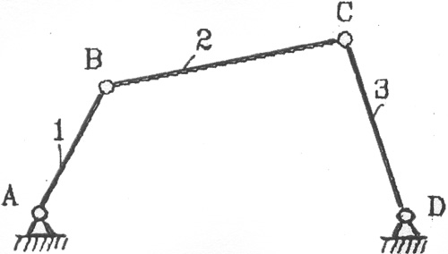
The names of mechanisms are usually determined by the names of their input and output links or the characteristic link included in their composition.
Depending on the laws of motion of the input and output links, this mechanism can be called crank-rocker, double crank, double rocker, rocker-crank.
The articulated four-link is used in machine tool building, instrument making, as well as in agricultural, food, snowplow and other machines.

If we replace a rotational pair in a hinged four-link, for example D , to translational, then we get the well-known crank-slider mechanism (Fig. 2.2).
Rice. 2.2. Various types of crank-slider mechanisms:
1 crank 2 - connecting rod; 3 - slider
The crank-slider (slider-crank) mechanism has found wide application in compressors, pumps, internal combustion engines and other machines.
Replacing a rotational pair in a hinged four-link FROM to translational, we get a rocker mechanism (Fig. 2.3).
On p and c .2.3, in the rocker mechanism is obtained from a hinged four-link by replacing rotational pairs in it C and O for progressive.
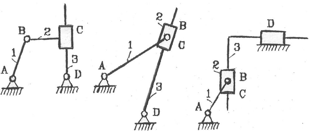
Rocker mechanisms have found wide application in planers due to their inherent property of the asymmetry of the working and idle move. Usually they have a long working stroke and a fast idle stroke that ensures the return of the cutter to its original position.
Rice. 2.3. Various types of rocker mechanisms:
1 crank; 2 stone; 3 wings.
Hinge-lever mechanisms have found great use in robotics (Fig. 2.4).
The peculiarity of these mechanisms is that they have a large number degrees of freedom, which means they have many drives. The coordinated operation of the drives of the input links ensures the movement of the gripper along a rational trajectory and to a given place in the surrounding space.
Widespread application in engineeringcam mechanisms. With the help of cam mechanisms, it is structurally the easiest way to get almost any movement of the driven link according to a given law,
There is currently big number varieties of cam mechanisms, some of which are shown in Fig. 2.5.

The necessary law of motion of the output link of the cam mechanism is achieved by giving the input link (cam) an appropriate shape. The cam can perform rotational (Fig. 2.5, a, b ), translational (Fig. 2.5, c, g ) or complex movement. The output link, if it makes a translational movement (Fig. 2.5, a, in ), called a pusher, and if rocking (Fig. 2.5, G ) - rocker. To reduce friction losses in the higher kinematic pair AT use an additional link-roller (Fig. 2.5, G ).
Cam mechanisms are used both in working machines and in various kinds of command devices.
Very often, in metal-cutting machines, presses, various instruments and measuring devices, screw mechanisms are used, the simplest of which is shown in fig. 2.6:
Rice. 2.6 Screw mechanism:
1 - screw; 2 - nut; A, B, C - kinematic pairs
Screw mechanisms are usually used where it is necessary to convert rotational motion into interdependent translational motion or vice versa. The interdependence of movements is established by the correct selection of the geometric parameters of the screw pair AT .
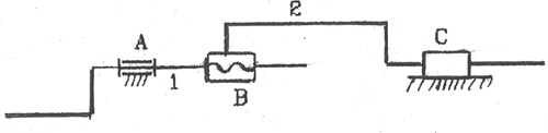
Wedge mechanisms (Fig. 2.7) are used in different kind clamping devices and fixtures in which it is required to create a large output force with limited input forces. A distinctive feature of these mechanisms is the simplicity and reliability of the design.
Mechanisms in which the transfer of motion between contacting bodies is carried out due to friction forces are called frictional. The simplest three-link friction mechanisms are shown in fig. 2.8

Rice. 2.7 Wedge mechanism:
1, 2 - links; L, V, C - kinematic feasts.

Rice. 2.8 Friction mechanisms:
a - friction mechanism with parallel axes; b - friction mechanism with intersecting axes; in - rack and pinion friction mechanism; 1 - input roller (wheel);
2 output roller (wheel); 2" - rail
Due to the fact that the links 1 and 2 attached to each other, along the line of contact between them, a friction force arises, which drags the driven link along with it 2 .
Friction gears are widely used in devices, tape drives, variators (mechanisms with smooth speed control).
For transmission rotary motion according to a given law, various types of gears are used between shafts with parallel, intersecting and intersecting axes mechanisms . With the help of gears, it is possible to transfer motion both between shafts withfixed axles, so with moving in space.
Gear mechanisms are used to change the frequency and direction of rotation of the output link, the summation or separation of movements.

On fig. 2.9 shows the main representatives of gears with fixed axles.
Fig 2.9. Gear drives with fixed axles:
a - cylindrical; b - conical; in - end; g - rack;
1 - gear; 2 - gear; 2 * rail
The smaller of the two meshing gears is called gear, and more - gear wheel.
The rack is a special case of a gear wheel in which the radius of curvature is equal to infinity.

If the gear train has gears with movable axles, then they are called planetary (Fig. 2.10):
Planetary gears, however, compared to fixed axle gears, allow the transfer of greater power and gear ratios with a smaller number of gears. They are also widely used in the creation of summing and differential mechanisms.
The transmission of movements between intersecting axes is carried out using a worm gear (Fig. 2.11).

A worm gear is obtained from a screw-nut transmission by cutting the nut longitudinally and folding it twice in mutually perpendicular planes. Worm gear has the property of self-braking and allows you to implement large gear ratios in one stage.
Rice. 2.11. Worm-gear:
1 - worm, 2 - worm wheel.
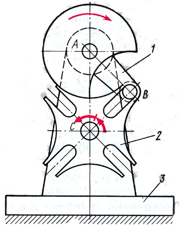
Intermittent motion gear mechanisms also include the Maltese cross mechanism. On fig. З-Л "2. shows the mechanism of the four-blade "Maltese cross".
The mechanism of the "Maltese cross" converts the continuous rotation of the leading even - crank 1 with a lantern 3 into the intermittent rotation of the "cross" 2 , lantern 3 enters the radial groove of the "cross" without impact 2 and turns it to the corner where z is the number of grooves.
To carry out movement in only one direction, ratchet mechanisms are used. Figure 2.13 shows a ratchet mechanism, consisting of a rocker arm 1, a ratchet wheel 3 and pawls 3 and 4.

When swinging the rocker 1 rocking dog 3 imparts rotation to the ratchet wheel 2 only when moving the rocker arm counterclockwise. To hold the wheel 2 from spontaneous clockwise rotation when the rocker moves against the clock, a locking pawl is used 4 .
Maltese and ratchet mechanisms are widely used in machine tools and instruments,
If it is necessary to transfer to relatively long distance mechanical energy from one point in space to another, then mechanisms with flexible links are used.
Belts, ropes, chains, threads, ribbons, balls, etc. are used as flexible links that transmit movement from one even of the mechanism to another,
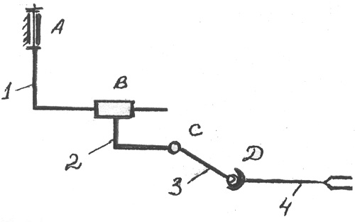
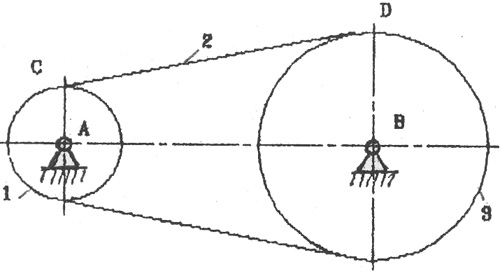
On fig. 2.14 shows a block diagram of the simplest mechanism with a flexible link.
Gears with flexible links are widely used in mechanical engineering, instrument making and other industries.
The most typical simple mechanisms have been considered above. mechanisms are also given in special Literature, pa-certificates and reference books, for example, such as.
Structural formulas of mechanisms.
There are general patterns in the structure (structure) of various mechanisms that relate the number of degrees of freedom W mechanism with the number of links and the number and type of its kinematic pairs. These patterns are called the structural formulas of mechanisms.
For spatial mechanisms, Malyshev's formula is currently the most common, the derivation of which is as follows.
Let in a mechanism with m links (including the rack), - the number of one-, two-, three-, four- and five-moving pairs. Let us denote the number of moving links. If all moving links were free bodies, total number degrees of freedom would be 6 n . However, each single-moving pair V class imposes on the relative movement of the links forming a pair, 5 bonds, each two-moving pair IV class - 4 bonds, etc. Therefore, the total number of degrees of freedom, equal to six, will be reduced by the amount
where is the mobility of a kinematic pair, is the number of pairs whose mobility is equal to i . The total number of superimposed connections may include a certain number q redundant (repeated) connections that duplicate other connections without reducing the mobility of the mechanism, but only turning it into a statically indeterminate system. Therefore, the number of degrees of freedom of the spatial mechanism, which is equal to the number of degrees of freedom of its moving kinematic chain relative to the rack, is determined by the following Malyshev formula:
or in shorthand
(2.2)
for mechanism statically determinate system, for - statically indeterminate system.
In the general case, the solution of equation (2.2) is a difficult problem, since the unknown W and q ; the available solutions are complex and are not considered in this lecture. However, in a particular case, if W , equal to the number of generalized coordinates of the mechanism, found from geometric considerations, from this formula you can find the number of redundant connections (see Reshetov L. N. Designing rational mechanisms. M., 1972)
(2.3)
and solve the problem of the static determinability of the mechanism; or, knowing that the mechanism is statically determined, find (or check) W.
It is important to note that the structural formulas do not include the sizes of links, therefore, in the structural analysis of mechanisms, one can assume them to be any (within certain limits). If there are no redundant connections (), the assembly of the mechanism occurs without deformation of the links, the latter seem to self-adjust; therefore, such mechanisms are called self-aligning. If there are redundant connections (), then the assembly of the mechanism and the movement of its links become possible only when the latter are deformed.
For flat mechanisms without redundant links structural formula bears the name of P. L. Chebyshev, who first proposed it in 1869 for lever mechanisms with rotational pairs and one degree of freedom. At present, the Chebyshev formula is extended to any flat mechanisms and is derived taking into account excess constraints as follows
Let in a flat mechanism with m links (including the rack), - the number of movable links, - the number of lower pairs and - the number of higher pairs. If all the moving links were free bodies making a plane motion, the total number of degrees of freedom would be equal to 3 n . However, each lower pair imposes two bonds on the relative movement of the links that form the pair, leaving one degree of freedom, and each higher pair imposes one bond, leaving 2 degrees of freedom.
The number of superimposed bonds may include a certain number of redundant (repeated) bonds, the elimination of which does not increase the mobility of the mechanism. Consequently, the number of degrees of freedom of a flat mechanism, i.e., the number of degrees of freedom of its movable kinematic chain relative to the rack, is determined by the following Chebyshev formula:
(2.4)
If known, from here you can find the number of redundant connections
(2.5)
The "p" index refers to the fact that we are talking about an ideally flat mechanism, or more precisely, about its flat scheme, since due to manufacturing inaccuracies, a flat mechanism is to some extent spatial.
According to formulas (2.2)-(2.5), a structural analysis of existing mechanisms and a synthesis of structural diagrams of new mechanisms are carried out.
Structural analysis and synthesis of mechanisms.
Influence of redundant connections on the performance and reliability of machines.
As mentioned above, with arbitrary (within certain limits) sizes of links, a mechanism with redundant links () cannot be assembled without deforming the links. Therefore, such mechanisms require increased manufacturing accuracy, otherwise, during the assembly process, the links of the mechanism are deformed, which causes the loading of kinematic pairs and links with significant additional forces (in addition to those basic external forces, for the transmission of which the mechanism is intended). With insufficient accuracy in the manufacture of a mechanism with excessive links, friction in kinematic pairs can increase greatly and lead to jamming of the links, therefore, from this point of view, excessive links in mechanisms are undesirable.
As for redundant links in the kinematic chains of the mechanism, when designing machines, they should be eliminated or left to a minimum amount if their complete elimination turns out to be unprofitable due to the complexity of the design or for some other reasons. In the general case, the optimal solution should be sought, taking into account the availability of the necessary technological equipment, the cost of manufacturing, the required service life and the reliability of the machine. Therefore, this is a very difficult task for each specific case.
We will consider the methodology for determining and eliminating redundant links in the kinematic chains of mechanisms using examples.
Let a flat four-link mechanism with four single-moving rotational pairs (Fig. 2.15, a ) due to manufacturing inaccuracies (for example, due to the non-parallelism of the axes A and D ) turned out to be spatial. Assembly of kinematic chains 4 , 3 , 2 and separately 4 , 1 does not cause difficulties, but points B , B can be placed on the axis X . However, to assemble a rotational pair AT , formed by links 1 and 2 , it will be possible only by combining the coordinate systems Bxyz and B x y z , which requires a linear displacement (deformation) of the point B link 2 along the x-axis and angular deformations of the link 2 around the x and z axes (shown by arrows). This means that there are three redundant bonds in the mechanism, which is also confirmed by formula (2.3): . In order for this spatial mechanism to be statically determinable, its other structural scheme is needed, for example, shown in Fig. 2.15, b , where The assembly of such a mechanism will take place without tightness, since the alignment of the points B and B will be possible by moving the point FROM in a cylindrical pair.
A variant of the mechanism is possible (Fig. 2.15, in ) with two spherical pairs (); In this case, apart frombasic mobilitymechanism appearslocal mobility- the ability to rotate the connecting rod 2 around its axis sun ; this mobility does not affect the basic law of movement of the mechanism and can even be useful in terms of leveling the wear of the hinges: connecting rod 2 during the operation of the mechanism, it can rotate around its axis due to dynamic loads. The Malyshev formula confirms that such a mechanism will be statically determinate:

Rice. 2.15
The most simple and effective method elimination of redundant connections in the mechanisms of devices - the use of a higher pair with a point contact instead of a link with two lower pairs; the degree of mobility of the flat mechanism in this case does not change, since, according to the Chebyshev formula (at):
On fig. 2.16, a, b, c an example of eliminating redundant links in a cam mechanism with a progressively moving roller pusher is given. Mechanism (Fig. 2.16, a ) - four-link (); except for the main mobility (cam rotation 1
) there is local mobility (independent rotation of a round cylindrical roller 3
around its axis) Consequently, . The flat scheme has no redundant connections (the mechanism is assembled without interference). If, due to inaccuracies in manufacturing, the mechanism is considered spatial, then with linear contact of the roller 3 with cam 1 according to Malyshev's formula at , we obtain, but under a certain condition. Kinematic pair cylinder - cylinder (Fig. 2.16, 6
) when the relative rotation of the links is impossible 1 , 3 around the z-axis would be a tripartite pair. If such a rotation, due to inaccuracies in manufacturing, takes place, but is small, and linear contact is practically preserved (under loading, the contact patch is close to a rectangle in shape), then this 
the kinematic pair will be four-movable, therefore, and
Fig.2.17
Reducing the class of the highest pair by using a barrel-shaped roller (five-moving pair with point contact, Fig. 2.16, in ), we obtain for and - the mechanism is statically determinate. However, it should be remembered that the linear contact of the links, although it requires increased manufacturing accuracy, allows you to transfer greater loads than point contact.
In Fig. 2.16, d, e another example is given of eliminating redundant connections in a four-link gear (, contact of the teeth of the wheels 1, 2 and 2, 3 - linear). In this case, according to the Chebyshev formula, - the flat scheme has no redundant connections; according to the Malyshev formula, the mechanism is statically indeterminate, therefore, high manufacturing accuracy will be required, in particular, to ensure the parallelism of the geometric axes of all three wheels.
Replacing idler teeth 2 on barrel-shaped (Fig. 2.16, d ), we obtain a statically determinate mechanism.
Kinematic couple movable conjugation of two solid links, imposing restrictions on their relative movement by the conditions of communication. Each of the link conditions eliminates one degree of freedom ,
that is, the possibility of one of 6 independent relative motions in space. In a rectangular coordinate system, 3 are possible translational movements(in the direction of 3 coordinate axes) and 3 rotational (around these axes). According to the number of communication conditions S K. p. are divided into 5 classes. Number of degrees of freedom K. p. W=6-S. Within each class, K. items are divided into types according to the remaining possible relative movements of the links. According to the nature of the contact of the links, lower K. p. are distinguished - with contact along surfaces, and higher ones - with contact along lines or at points. Higher K. items are possible for all 5 classes and many types; lower - only 3 classes and 6 species ( fig.1
). A distinction is also made between geometrically closed and non-closed c.p. rice. one
), and secondly, a pressing force is required for closing, the so-called. force closure (for example, in a cam mechanism). Conventionally, movable couplings with several intermediate rolling elements (for example, ball and roller bearings) and with intermediate deformable elements (for example, the so-called backlash-free hinges of devices with flat springs) are referred to as k. rice. 2
). N. Ya. Niberg.
Big soviet encyclopedia. - M.: Soviet Encyclopedia. 1969-1978 .
See what "Kinematic pair" is in other dictionaries:
The connection of 2 links of the mechanism, allowing their relative movement. The kinematic pair, in which the links touch on the surface, is called the lower one (for example, a rotational hinge, a translational slider and a guide). Kinematic pair, ... ... Big Encyclopedic Dictionary
kinematic pair- pair Connection of two adjoining links, allowing their relative movement. [Collection of recommended terms. Issue 99. Theory of mechanisms and machines. USSR Academy of Sciences. Committee of Scientific and Technical Terminology. 1984] Topics theory ... ... Technical Translator's Handbook- kinematinė pora statusas T sritis fizika atitikmenys: angl. kinematic pair vok. kinematisches Elementenpaar, n rus. kinematic pair, f pranc. paire cinématique, f … Fizikos terminų žodynas
The connection of two adjoining links, allowing them to be related. traffic. Surfaces, lines, points, to which a link can come into contact with another link, called. link elements. K. p. are divided into lower (contact surfaces) and higher ... ... Big encyclopedic polytechnic dictionary
kinematic pair- kinematic pair Connection of two rigid bodies of the mechanism, allowing their given relative movement. Code IFToMM: 1.2.3 Section: GENERAL CONCEPTS OF THE THEORY OF MECHANISMS AND MACHINES ... Theory of mechanisms and machines
pair- kinematic pair; pair A connection of two contiguous links, allowing relative movement from them. couple of forces; couple system two parallel forces, equal in absolute value and directed in opposite directions ...
top pair- A kinematic pair in which the required relative motion of the links can only be obtained by touching its elements along lines and at points ... Polytechnic terminological explanatory dictionary


