Determination of the degree of mobility. Structural analysis and synthesis of mechanisms. Types of Assur groups II class
2 Structural analysis and synthesis of mechanisms
2.1 Determination of the number of degrees of freedom of the kinematic chain
As noted above, the number of input links for the transformation of a kinematic chain into a mechanism must be equal to the number of degrees of freedom of this kinematic chain.
The number of degrees of freedom of the kinematic chain in this case means the number of degrees of freedom of the movable links relative to the rack (the link taken as fixed). However, the rack itself in real space can move.
Equivalent Communication Mobility Authorized Authorized Prohibited Authorized Authorized Authorized. A series of combination of ball joint and sliding joint connection. Notes: Series connection bonding has the advantage of replacing a fragile contact point or line type with a technologically more interesting contact surface, as they reduce pressure and thereby improve connection reliability. If, however, mobility is allowed by each elementary link, there is an occurrence of internal mobility of the part contained in the serial connection.
For example, any motionless body on the Earth has a zero degree of freedom, but in the World space, together with the Earth, it moves using all six degrees of freedom. Another example: the kinematic chain underlying piston engine, has one degree of freedom relative to the rack (the link taken in the study for a fixed one, which consists of a cylinder attached to the crankcase and the frame or body of a car, motorcycle or other machine), although the rack itself also moves when the car moves.
It can be rotation or translation without causing any movement of other parts. Using the previous example on parallel links for searching and linking. Thus, unlike a serial connection, a connection involving several elementary links located in parallel to each other reduces the amount of mobility between the two parts. This suppression of degrees of mobility is carried out through the transfer of mechanical actions between two strong ones, due to the existence of certain components of the transmitted torsor, given that: - this mobility is forbidden in the translation along the axis corresponds to a non-zero value of the component of the key sum component. - Mobility is prohibited rotation around the axis results from a non-zero value of the time component of the key element along this axis.
However, regardless of whether the machine is moving or not, the nature of the movement of the piston engine links relative to the rack remains unchanged.
Let us introduce the following notation:
k is the number of links of the kinematic chain
p 1 - the number of kinematic pairs of the first class in a given chain
p 2 - the number of pairs of the second class
p 3 - the number of pairs of the third class
A link is isostatic if the number of unknowns of the associated transmitted torsor is equal. The reference is indeterminate if the number of unknowns of the transmitted key exceeds. The number of equations provided by the fundamental principle. Degree in Applied Engineering 11.
He offers below two options using elementary links parallel to the swivel. The connection is an annular linear link of the axis, the link is the axis of the axis of rotation. Specifies the static twist of the line. Determine the degree of link hyperstatism. In a kinematic study, define a torsor equivalent to two links in parallel and. and hyperstatic unknowns. kinematic bond equivalent to two bonds and. so that the connection, which is equivalent to two links, and is an isostatic pivot link, offers several possible modifications of the link, and the link remains unchanged.
p 4 - the number of pairs of the fourth class
p 5 is the number of pairs of the fifth class.
The total number of degrees of freedom k of free links placed in space is 6k. In a kinematic chain, they are connected into kinematic pairs (i.e., connections are superimposed on their relative movement).
In addition, a kinematic chain with a rack (a link taken as a fixed one) is used as a mechanism. Therefore, the number of degrees of freedom of the kinematic chain will be equal to total number degrees of freedom of all links minus the constraints imposed on their relative motion:
Static ties torsos and have. The connection diagram looks like this. Static Torque: By the fundamental principle of static, it demonstrates that. Kinematic deformation: using the law of composition of kinematic torrs, we get.
Movement exists between and all connections. Hyperstatism and Mobility: Writing Relationships. Equal to the number of kinematic unknowns that do not depend on the equivalent connection. A part has internal mobility in the mechanism if it can have a movement that does not cause any movement of other parts of the mechanism. Hence, an equivalent relationship.
W=6k– ∑ S i
The number of bonds imposed by all pairs of class I is equal to their number, since each pair of the first class imposes one connection on the relative movement of the links connected in such a pair; the number of bonds imposed by all pairs of class II is equal to their doubled number (each pair of the second class imposes two bonds), etc.
Α = α2 β = β2 γ = γ1 γ 2 equivalents. Note that this ease of fabrication is partly offset by the more complex mechanism. Complexity is usually due to the introduction of intermediate components in series in bonds to increase the number of degrees of freedom. Ensuring that the surfaces to be joined are in contact. Therefore, an accurate knowledge of the theory of the screw of each link, which allows an assessment.
The isostatic design guides the setting of the exact position of the part relative to others. correct pressure between contact surfaces. Example: isostatic positioning Kelvin In this position, it is used, for example, to turn the turrets, isostatic and full coupling between parts and is carried out using a parallel combination of the following three connections:: connection point.: Annular linear connection, the axis of which passes through the center.
All six degrees of freedom are taken away from the link, taken as fixed (six bonds are superimposed on the rack). In this way:
S 1 \u003d p 1, S 2 \u003d 2p 2, S 3 \u003d 3p 3, S 4 \u003d 4p 4, S 5 \u003d 5p 5, S rack \u003d 6,
and the sum of all connections
∑ S i =p 1 +2p 2 +3p 3 +4p 4 +5p 5 +6.
The result is the following formula for determining the number of degrees of freedom of a spatial kinematic chain:
The plane formed by the axis of the circular linear connection and the point of contact of the connection point. However, the indeterminate mechanism is often more rigid than the isostatic mechanism, which is also a factor in the positional accuracy of a part relative to another. Those who provide both positioning and maintaining room contact.
Its supports fall into two categories. Shown by relationships in a parallel study, the equivalent relationship thus obtained between the workpiece and the processing unit is isostatic and complete. Study maintaining contact provided by screws.
W=6k–p 1 –2p 2 –3p 3 –4p 4 –5p 5 –6.
Grouping the first and last terms of the equation, we get:
W=6(k–1)–p 1 –2p 2 –3p 3 –4p 4 –5p 5 ,
or finally:
W=6n–p 1 –2p 2 –3p 3 –4p 4 –5p 5 ,
where n is the number of moving links of the kinematic chain.
This equation is called structural formula general kinematic chain.
The formula was obtained for the first time (in a slightly different form) by P.I. Somov in 1887, and developed by A.P. Malyshev in 1923. Therefore, it is often called the Somov-Malyshev formula. In some textbooks, it is called the Malyshev formula - after the authorship of the final version.
Let acts on a helical mechanical action, known static unknown references can be determined. Linking the workpiece to the processing unit through the screw includes the following two serial links: point connection axis, applied licenses in mechanical engineering 20. Determine the theory of the screw equivalent of linking these two serial channels. Therefore, the equivalent connection between the assembly and the workpiece to the holding contact device is a loose connection.
This contact holding device does not add any static unknowns to the part positioning links already entered. Therefore, the equivalent relationship with part-to-assembly connections is always isostatic. In general, an equivalent relationship between two solids a contact retainer that does not provide relative positioning of solid particles shall be a loose joint. Such a relationship allows not to increase the degree of hyperstatism already obtained by the relationships of the relative positioning of two solids.
p 1 - the number of single-moving pairs (i.e. kinematic pairs providing one degree of freedom in relative motion),
p 2 is the number of two-moving pairs, etc.
That is, the index in this case shows not the number of bonds, but the number of degrees of freedom, and in the formula the designations p 1 and p 5, as well as p 2 and p 4 are interchanged. Therefore, when using various textbooks, it is necessary to carefully monitor the interpretation of the author, because, unfortunately, often different authors The same designation has different meanings. As a result, with the same notation, the same formulas have different forms.
The continuous circuit is closed. In the case of a closed continuous chain consisting of solid bodies assembled in succession by links, the bond graph looks like this: a closed continuous chain is also called a simple chain or loop. It is also shown that the degree of mobility m of a closed continuous chain is: m = 6n - gs, where m is the number of independent kinematic unknowns of a closed continuous chain. This ratio allows us to calculate the degree of hyperstatism, knowing the degree of mobility. Kinematic research.
It can also be said that the degree of mobility of a closed continuous chain is the number of independent kinematic unknowns that must be fixed to determine all the others. Consider the mechanism for controlling the rod by an eccentric. Suggest a solution to make this mechanism isostatic. To add these three torsos, they must be expressed at the same point.
Manipulators and industrial robots use open (open) kinematic chains. In such chains, the number of moving links is equal to the total number of kinematic pairs:
n=p 1 +2p 2 +3p 3 +4p 4 +5p 5 ,
W=6(p 1 +2p 2 +3p 3 +4p 4 +5p 5)–p 1 –2p 2 –3p 3 –4p 4 –5p 5 ,
or finally:
W=5p 1 +4p 2 +3p 3 +2p 4 +p 5 .
Thus, the number of degrees of freedom of an open kinematic chain is equal to the sum of the mobilities (degrees of freedom) of the kinematic pairs included in this chain. In addition to degrees of freedom, the quality of work of manipulators and industrial robots is greatly influenced by their maneuverability.
Applied degree in mechanical engineering 25. Note. This relation makes it possible to calculate the degree of hyperstatism, knowing the degree of mobility of a complex chain. The mobile jaw has a slide connection. Applied license in mechanical engineering 26. Inference Hyperstatic unknown mechanisms are determined from a static study.
Let's put: regardless of this mechanism. its degree of hyperstatism. Do the dimensional and angular conditions of the relative position of the links correspond? These six equations are independent. Hence the degree of mobility of the chain. Applied licensee in mechanical engineering 27.
Maneuverability is the number of degrees of freedom of the manipulator with a fixed grip. It determines the ability of the manipulator (industrial robot) to bypass obstacles and is calculated by the following formula:
where M is the maneuverability of the manipulator.
As noted above, a significant number of mechanisms used in practice are flat mechanisms (that is, they are based on flat kinematic chains). Placing a kinematic chain in a plane imposes three general constraints on the movement of all links of this chain, so k free links placed in a plane have a total of 3k degrees of freedom.
This degree of mobility corresponds to three components. Movement from. COMMUNICATIONS FROM THE COMMISSION TO THE EUROPEAN PARLIAMENT, THE COUNCIL, THE EUROPEAN ECONOMIC AND SOCIAL COMMITTEE AND THE COMMITTEE OF THE REGIONS. European Low Emissions Mobility Strategy.
Low-emission mobility is an important element in the overall transition to a low-carbon circular economy that Europe needs to remain competitive and meet the mobility needs of people and goods. Transport accounts for almost a quarter of greenhouse gas emissions in Europe; it is also the main cause of air pollution in cities. Europe's response to these challenges is an irreversible shift towards low carbon mobility and air pollutants. Emissions of pollutants in the air that are harmful to our health must be reduced immediately.
If the kinematic chain, which, in accordance with the Chebyshev formula, has a zero degree of freedom, turns out to be movable, this means that there are passive (excessive) links in this chain. When studying the mechanism in this case, the links that create passive connections are simply removed from consideration.
Figure 4a shows the kinematic diagram of the ellipsograph mechanism (W=3 ⋅ 3 – 2 ⋅ 4 = 1). It has the following properties: points A and B move translationally along the X and Y axes as belonging to sliders 1 and 3.
The transition to low-emission mobility has already begun globally and is accelerating. This gives great opportunities. This allows European automakers to modernize, actively promote new technologies and restore consumer confidence. It is also an opportunity for other industries and manufacturers to maintain global standards and export their products. It also provides an opportunity for innovative energy companies and service providers, as well as investors, to promote sustainable growth and create new jobs.
In this case, the point M describes an ellipse with a minor semiaxis equal to the segment AM and located along the Y axis, and with a major semiaxis BM located along the X axis (i.e., an ellipse extended along the X axis); point N describes an ellipse with semi-minor axis BN and semi-major axis AN, extended along the Y axis.
Point C (middle of segment AB) describes an "ellipse" with equal semi-axes, i.e. circle. If some link 5 is attached by hinges to a fixed point O (the origin of coordinates) and to any point on the link AB (for example, to point N - Figure 4b), then we get a fixed system (truss):
Its current pace should be accelerated through the current low-emission mobility strategy, while providing the necessary mobility for an efficient domestic market and global connectivity. This will require a wide range of activities. The Action Plan sets out the actions that the Commission intends to take, in accordance with the principles and processes for improving legislation, to ensure that all proposed measures are factual, effective, efficient, proportionate and fully respect the principle of subsidiarity.
W = 3 ⋅ 4 – 2 ⋅ 6 = 0.
However, if link 5 is attached with the second hinge to link AB at point C (Figure 4c), then the movement of point C belonging to link 5 and the movement of point C belonging to link AB become coordinated - both points move along the same trajectory ( along a circle of radius OC).
In this only particular case, the kinematic chain becomes movable (the formula cannot "foresee" such special case- it gives the result for the general case of the corresponding combination of links and kinematic pairs). In this case, link 5 imposes a passive (excessive) connection, and this link can be ignored when studying the mechanism.
Because the automobile transport responsible for more than 70% of greenhouse gas emissions from transport and much of air pollution, this is an area where efforts will be focused, but all transport sectors can and should contribute. Through its initiatives, the EU will create an enabling environment and provide strong incentives for low-emission mobility. The measures announced in this communication are part of a holistic approach that requires the long-term involvement of all stakeholders, including Member States, who will be required to contribute in accordance with their responsibilities.
The presence of passive links can be established by constructing a new position of a given kinematic chain with a zero (or negative) degree of freedom for the same link sizes. If the circuit is built in other positions, it has passive connections. If the dimensions do not fit together in a new position, then this is indeed a fixed system - a truss (with a negative number of degrees of freedom - the truss is statically indeterminate).
Researchers, manufacturing and service sectors in Europe must continue to innovate and make their strategic choices with a mid-century goal. They will need the right incentives and investments at the right time to bring their innovations to market in Europe and the world. Regions and cities will also be important players in finding low-emission mobility solutions where challenges are felt best, and ultimately the choice of gender for mobile users will determine how successful we are.
Only thanks permanent action of all participants, Europe will be able to successfully transform its transport system, which is crucial for its prosperity and the well-being of its citizens. Regulatory Framework for Low Emission Mobility.
Extra degrees of freedom - if the mechanism has a movement of any link that does not affect the movement of the other links of this mechanism, then it gives an extra degree of freedom.

Usually, an extra degree of freedom is formed in the presence of a round roller. Rotating around its own axis, it does not change the nature of the movement of the remaining links.
Figure 5a shows a mechanism with a non-circular roller - here the position of the pusher 2 will depend not only on the position of the cam, but also on the position of the roller. That is, the mechanism really has two degrees of freedom. In the mechanism in Figure 5b, the roller is round and its angle of rotation does not affect the position of the pusher - the position of the pusher is completely determined by the position of the cam.
Thus, in fact, the mechanism has one effective degree of freedom (rotation of the roller around its own axis formally gives the second degree of freedom, but this movement does not affect the movement of the remaining links of the mechanism).
When investigating a mechanism, it is convenient to get rid of an extra degree of freedom. To do this, it is necessary to replace the practical profile with a theoretical one - an equidistant profile passing through the center of the roller, and remove the roller from consideration (Figure 5c).
Determination of the degree of mobility of the mechanism
Determination of the degree of mobility of a spatial kinematic chain
Let we have n links from which the kinematic chain is assembled. Until the links are connected into kinematic pairs, each of them has six degrees of freedom (degrees of freedom). All links before joining into a kinematic chain therefore had 6n degrees of mobility. After assembling the links into a kinematic chain, we will get kinematic pairs of various classes (with different degrees of mobility). Suppose that our kinematic chain has kinematic pairs of all five classes. We accept the following notation:
P 5 - the number of kinematic pairs of the fifth class in the kinematic chain formed by us,
R 4 - the number of kinematic pairs of the fourth class,
P 3 - the number of kinematic pairs of the third class,
P 2 - the number of kinematic pairs of the second class,
P 1 - the number of kinematic pairs of the first class.
Each kinematic pair limits the movement of links, takes away from them as many degrees of freedom as its class. Each kinematic pair of the 5th class selects 5 degrees of freedom from the links. All pairs of the fifth class will be taken away from the links 5P 5 degrees of freedom, the fourth class - 4P 4, the third - 3P 3, the second - 2P 2, the first - 1P 1. If we subtract all the lost degrees of freedom from the total number of degrees of freedom of the links 6n, we get the number of degrees of freedom of the kinematic chain W:
W \u003d 6n-5P 5 -4P 4 -3P 3 -2P 2 -1P 1. (one)
The degree of mobility of the mechanism it is customary to call the number of independent coordinates that are extremely important to set to determine the positions of the links of the mechanism in the coordinate system rigidly connected to the rack.
The mechanism differs from the kinematic chain in that it has one link completely fixed. The fixed link lost all six degrees of freedom. Therefore, the number of moving links in the mechanism is n-1. Substituting the number of moving links n-1 into formula (1), we obtain a formula for determining the degree of mobility of the mechanism:
W=6(n-1)-5P 5 -4P 4 -3P 3 -2P 2 -1P 1 . (2)
Formula (2) was first obtained by Malyshev for spatial mechanisms.
Consider the Malyshev formula for determining the degree of mobility of flat mechanisms. All links of a flat mechanism can have three degrees of mobility, and kinematic pairs, respectively, can have 1 or 2 degrees of mobility. If planar kinematic pairs are considered by classes, then they are only of the fifth and fourth classes. At the same time, it is extremely important to take into account that the total number of degrees of freedom of all links of the flat mechanism is 3 (n-1). Pairs of the fifth class lose two degrees of mobility, the fourth - one. Thus, the degree of mobility of the flat mechanism must be determined by the formula:
W=3(n-1)-2P 5 -P 4 . (3)
Formula (3) for determining the degree of mobility of a flat mechanism was first obtained by P. L. Chebyshev.
Taking into account the dependence of the number of general conditions of relations imposed on the mechanism, the mechanisms are divided into families.
The families of mechanisms and their structural formulas are shown in Table 1.
Table 2.1 Structural formulas of various families of mechanisms

Consider the application of the structural formula of P. L. Chebyshev on a specific example. Figure 5 shows an articulated four-link.
1e- link- crank- commits rotary motion around the O axis ( full turn);
2e- link AB - connecting rod - makes a plane-parallel movement;
3e- BC link - rocker arm (or balancer) - performs a reciprocating rotational movement around the C axis ( incomplete turnover);
4e- OS link - rack (bed) - fixed link.
Number of links n=4. Kinematic pairs: 4-1, 1-2, 2-3, 3-4. We have 4 single-moving pairs 5 th class. The relative motion of all links is flat. The mechanism is flat. We determine the degree of its mobility according to the formula of Chebyshev P. L.:
W=3(n-1)-2P 5 -P 4 =3(4-1)-2×4-0=1.
The mechanism has a degree of mobility equal to 1. This means that it is enough to set one coordinate to any link of the mechanism in the coordinate system rigidly connected to the frame in order to determine the positions of all other links. For example, in our case, it is enough to set the angle of rotation of the crank j 1 .
 Passive Links and Redundant Links
Links and kinematic pairs, which do not affect the nature of the movement of the mechanism as a whole, are called redundant (extra) links and pairs, and the bonds conditioned by them are called passive bonds.
When determining the degree of mobility of the mechanism, excess links and kinematic pairs should not be taken into account.
In complex rod mechanisms, it is not always possible to determine the degree of mobility by eye. In these cases, it is extremely important to use the Chebyshev formula.
 Let's define W of the double parallelogram mechanism (Figure 6). Here AB=BC=KM=MN; AN || BM || CK; AN=BM=CK and AC || K.N. With such a ratio of links, the mechanism has W = 1, i.e. it is enough to set the position of link 1 by angle j 1 to determine the positions of all other links. If you fix link 1 in any position, then the remaining links will be motionless. We define W by the Chebyshev formula. Number of links - n = 5, kinematic pairs 5 th class P 5 \u003d 6, the number of kinematic pairs of the fourth class - P 4 \u003d 0.
W=3(n-1)-2P 5 -P 4 =3(5-1)-2×6-0=0.
If W=0, then there should be not a mechanism, but a rigid farm. We see that the mechanism can carry out movement. In case if in this mechanism mentally remove link 5 (or 2), then the nature of the movement of the remaining links will remain unchanged. The mechanism turns into an ordinary four-link, W of which we have already determined - W=1. When link 5 is eliminated, 2 kinematic pairs are simultaneously eliminated: 5-1, 5-3. Therefore, in this mechanism, one link and two kinematic pairs are redundant.
 Consider another example - the Marcus mechanism, often used as a drive for a swinging conveyor (Figure 7). Number of links n=6. Kinematic pairs: 6-1, 1-2, 2-3, 2-4, 3-4, 3-6, 4-5, 5-6 all fifth class P 5 = 8, P 4 = 0 .
We define W by the Chebyshev formula:
W=3(n-1)-2P 5 -P 4 =3(6-1)-2×8-0=-1.
According to the scheme of the mechanism, it can be seen that it will work and W=1.
Let there be no direct connection of links 2-3. Links 3, 4, 5 will still take a position corresponding to the angle of rotation j 1 of link 1, since links 1, 2, 4 must be fixed at this angle. The same can be obtained if the kinematic pair 2-4 or 4-3 is removed. Here one kinematic pair is redundant. It can be ignored. Then:
W=3(6-1)-2×7=1.
At the same time, we note that the elimination of the link entails the elimination of some kinematic pairs.
Hosted on ref.rf
The elimination of kinematic pairs (the termination of the contact of the links) does not entail the inevitable elimination of the links included in it.
The connection of links, where 3 or more links are connected, is commonly called node. There is one kinematic pair in a node less than links.
 Excess kinematic pairs and links impose additional conditions on the accuracy of manufacturing the mechanism, however, despite this, a passive link or an extra connection is sometimes introduced into the mechanism in order to obtain any additional necessary qualities; increase in strength, decrease in friction, etc.
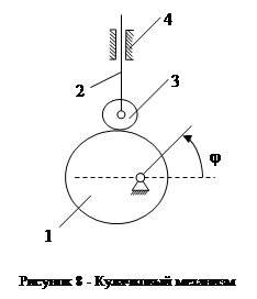
Let's determine W of the cam mechanism shown in Figure 2.8. Here the links are 1 - cam, 2 - pusher, 3 - roller, 4 - rack. Number of links n=4. Kinematic pairs 1-4, 2-4, 2-3 of the fifth class and 3-1 - the highest flat kinematic pair 4 th class.
When the cam is rotated through an angle j, the pusher will take a certain position. At first glance W=1. We define W by the Chebyshev formula:
W=3(4-1)-2×3-2=2.
There is an extra degree of mobility here. If the roller was fixedly fixed with a pusher, then W of the mechanism would be equal to one. Rotation of the roller in relation to the rest of the links has no effect. The angle of rotation of the roller is the extra degree of freedom of the mechanism.
An extra degree of freedom it is customary to call such a degree of freedom in the movement of some links, the elimination of which does not cause changes in the nature of the movement of other links for kinematic reasons.
This refers to the absolute or relative movement of the link. The elimination of an extra degree of freedom does not entail the elimination of the link.
Before using the Chebyshev formula, it is extremely important to mentally exclude passive constraints and extra degrees of freedom from consideration.
The Chebyshev formula generally gives the correct answer. In general cases, passive connections and extra degrees of freedom do not exist and exist only in special cases.
For example: the double parallelogram mechanism is a special case of the same mechanism when the links are not parallel (Figure 9a); the Marcus mechanism is a special case of the mechanism when the axes of the articulated joints of links 2, 4 do not match (Figure 9b); a round roller is a more particular case of the geometric shape of a roller round shape(Figure 9c).
Thus, the Chebyshev formula makes it possible to identify characteristics(in particular) mechanisms.
Determination of the degree of mobility of the mechanism - the concept and types. Classification and features of the category "Determination of the degree of mobility of the mechanism" 2014, 2015.


