Laboratory work on physics oge lever. Checking the laws of parallel connection of resistors for current strength. Determining the Properties of an Image Obtained with a Converging Lens
Set #1
Measuring the density of a substance
Using beaker, water, measuring cylinder, balance, weight, determine the density of cylinder #1 or #3. Make the necessary measurements and calculations and determine the density of the substance. Record the results of measurements and calculations in the reporting table.
On the answer sheet:
2) write down the formula for calculating the density solid body;
3) record the results of measurements and calculations in the reporting table.
Set №2
Buoyancy force measurement.
Using a school dynamometer with a measurement limit of 4N (c \u003d 0.1N), a glass of water, cylinder No. (1 or 3), assemble an installation to determine the buoyancy force (Archimedes force) acting on the cylinder.
On the answer sheet:
2) write down the formula for calculating the buoyancy force;
3) indicate the results of measurements of the weight of the cylinder in air and the weight of the cylinder in water;
4) write down the numerical value of the buoyancy force.
Set No. 3.
Spring stiffness measurement.
Using a tripod with a clutch and foot, (spring) two dynamometers, a ruler and three weights, assemble an experimental setup to determine the spring stiffness. Determine the stiffness of the spring by hanging one, two, three weights from it. Use a dynamometer to determine the weight of the loads.
On the answer sheet:
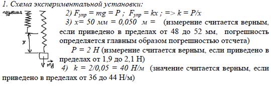
1) draw a drawing of the experimental setup;
2) write down the formula for calculating the stiffness of the spring;
3) indicate the results of measuring the weight of the weights and the elongation of the spring;
4) write down the numerical value of the spring stiffness.
Investigation of the dependence of the elastic force arising in the spring on the degree of deformation of the spring.
Using a tripod with a clutch and foot, (spring) two dynamometers, a ruler and three weights, assemble an experimental setup to study the dependence of the elastic force that occurs in the spring on the degree of deformation of the spring. Determine the stiffness of the spring by hanging one, two, three weights from it. Use a dynamometer to determine the weight of the loads.
On the answer sheet:
1) describe the procedure for performing the experiment, draw a drawing of the experimental setup;
2) indicate the results of direct measurements of the elastic force and displacement in the form of a table;
3) build a graph of the dependence of the elastic force on the deformation of the spring;
4) formulate a qualitative conclusion about the dependence of the elastic force arising in the spring on the degree of deformation of the spring.
Set No. 4.
Measurement of the coefficient of sliding friction.Using a carriage (bar) with a hook, a dynamometer, two weights, assemble an installation to determine the coefficient of sliding friction between the carriage and the table surface.
On the answer sheet:
1) draw a drawing of the experimental setup;
2) write down the formula for calculating the coefficient of sliding friction;
3) indicate the results of measuring the weight of the carriage with the load and the sliding friction force when the carriage with the loads moves along the surface of the table;
4) write down the numerical value of the coefficient of sliding friction.
Investigation of the dependence of the sliding friction force on the force of normal pressure.Using a wooden block with hooks on a thread, a dynamometer, 2 weights of (100+_20g), a guide rail, investigate the dependence of the friction force on the force of normal pressure.
in the answer sheet;
1) describe the procedure for performing the experiment;
2) write down the found value of the coefficient of friction for each measurement;
3) build a graph of the dependence of the friction force on the force of normal pressure;
4) draw a conclusion about the nature of the dependence of the friction force on the force of normal pressure.
Set number 5.
Conductor resistance measurement.
Using power supply direct current 4.5V, voltmeter, ammeter, key, rheostat, connecting wires, resistor No. 1 or No. 2, assemble an experimental setup to determine electrical resistance resistor.
On the answer sheet:
2) write down the formula for calculating electrical resistance;
3) indicate the results of voltage measurement at a current strength of 0.5A;
4) write down the numerical value of the electrical resistance.
Definition of work electric current
Using a 4.5V DC power supply, a voltmeter, an ammeter, a key, a rheostat, connecting wires, a resistor No. _ (1 or 2), assemble an experimental setup to determine the operation of an electric current on a resistor at a current strength of 0.5 A for 10 minutes.
On the answer sheet:
1) draw the electrical circuit of the experiment;
2) write down the formula for calculating the work of an electric current;
4) write down the numerical value of the electric current.
Determination of the power of electric current in a conductor.
Using a 4.5V DC power supply, a voltmeter, an ammeter, a key, a rheostat, connecting wires, a resistor No. _ (1 or 2), assemble an experimental setup to determine the power of the resistor.
On the answer sheet:
1) draw the electrical circuit of the experiment;
2) write down the formula for calculating the power of electric current;
3) indicate the results of voltage measurement at a current strength of 0.5A;
4) write down the numerical value of the power of the electric current.
Investigation of the dependence of the current strength arising in the conductor on the voltage at the ends of the conductor.
Using a 4.5V DC power supply, a voltmeter, an ammeter, a key, a rheostat, connecting wires, a resistor No. _ (1 or 2), assemble an experimental setup to study the dependence of the current strength that occurs in the conductor on the voltage at the ends of the conductor.
On the answer sheet:
1) describe the procedure for performing the experiment;
2) write down the found value of current and voltage for each measurement;
3) build a graph of current versus voltage;
4) draw a conclusion about the nature of the dependence of the current strength that occurs in the conductor on the voltage at the ends of the conductor.
Experimental verification of the rule for the current strength when two conductors are connected in parallel.
Using a current source (4.5 V), a voltmeter, a key, connecting wires, resistors marked R1 and R2, experimentally check the rule for current strength when two conductors are connected in parallel.
On the answer sheet:
2) measure the current across each of the resistors and overall strength current in the circuit when they are connected in parallel;
3) compare the total current in the circuit with the sum of the currents on each of the resistors, given that the error of direct measurements using a laboratory ammeter is 0.05A.
4) Make a conclusion about the validity or fallacy of the tested rule
Experimental verification of the rule for electrical voltage when two conductors are connected in series.
Using a current source (4.5 V), a voltmeter, a key, connecting wires, resistors marked R1 and R2, experimentally check the rule for electrical voltage when two conductors are connected in series.
On the answer sheet:
1) draw the electrical circuit of the experimental setup;
2) measure the voltage at the ends of each of the resistors and the total voltage at the ends of the circuit of two resistors when they are connected in series;
3) compare the total voltage across the two resistors with the sum of the voltages
on each of the resistors, given that the error of direct measurements using a laboratory voltmeter is 0.2 V.
Make a conclusion about the validity or fallacy of the rule being tested.
Set No. 6.
Optical power of a system of two lenses
Using two converging lenses, a ruler, a screen and a distant light source (illuminated window), check the validity of the following condition: the optical power of the system of two lenses is equal to the sum of the optical powers of each lens (D = D 1 + D2 ).
On the answer sheet:
- Sketch the scheme of the experiment (indicate the course of rays through two converging lenses installed side by side) and write down the formula for calculating the optical power of the lens.
- Determine the focal length of each of the two lenses and calculate the optical power for them.
- Position the lenses so that the main optical axis passes through the center of each lens and the lenses are in contact. Determine the focal length of the lens system and calculate the optical power.
- Check if the condition is true and write the output
Resizing the image when moving the subject from lens focus to dual focus.
On the answer sheet:
- Imagine how the image will change when the object is moved from the focus of the lens to the double focus.
- Sketch the scheme of the experiment (show the path of the rays if the object is between the focus and the double focus of the lens and if it is at a distance greater than the double focal length).
- Check your assumption. To do this, first determine the focal length. Then place the object at distances F
d > 2F, and for each of these options, determine the size of the image.
- Formulate and write down the conclusion.
Measuring the optical power of a lens
Using a converging lens No. _ (1 or 2), a ruler 20-30 cm long, a screen, a working body, determine the focal length and calculate the optical power of the lens.
On the answer sheet:
1) draw a drawing of the experimental setup;
2) write down the formula for calculating the optical power of the lens;
3) indicate the results of measuring the focal length of the lens;
4) write down the numerical value of the optical power of the lens.
Study of the dependence of the distance between the object and the lens on the distance between the lens and the image
Using a converging lens, a ruler, a screen, a lamp with a cap as an object, assemble an experimental setup to study the dependence of the distance between the object and the lens on the distance between the lens and the image.
On the answer sheet:
- Determine the focal length of the lens.
- Install the lamp alternately at distances F 2F and, having measured the distance between the lens and the image in each case, indicate the results of measuring the distances of these three cases in the form of a table.
- Formulate a conclusion about the dependence of the distance between the object and the lens on the distance between the lens and the image.
Set No. 7.
Determination of the period of oscillation of the pendulum.
To complete the task, use laboratory equipment: a tripod with a clutch and a foot; meter ruler (with an error of 5 mm); a ball with an attached thread 110 cm long; clock with a second hand (or stopwatch).
On the answer sheet
- Calculate the oscillation periods from the data obtained. Make a conclusion about the dependence of the period of oscillation of a mathematical pendulum on the length of the thread.
Plotting the dependence of the period of oscillation of the pendulum on the length of the thread.
To complete the task, use laboratory equipment: a tripod with a clutch and a foot; meter ruler (with an error of 5 mm); a ball with an attached thread 110 cm long; clock with a second hand (or stopwatch).
On the answer sheet
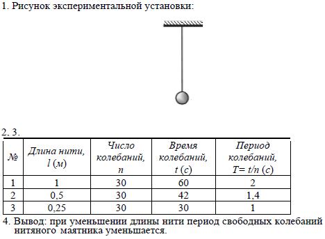
- Draw the scheme of the experiment.
- Write down the formula for calculating the period of oscillation of a mathematical pendulum.
- Measure the time of 30 oscillations for four lengths of the pendulum. Specify the measurement results.
- Calculate the oscillation periods from the data obtained. Plot a graph of the period of oscillation versus the length of the thread. Make a conclusion about the nature of the dependence of the period of oscillation of a mathematical pendulum on the length of the thread.
Investigation of the dependence of the period or frequency of oscillations of a mathematical pendulum on the length of the thread.
Using a tripod with a clutch and foot, a ball with a thread attached to it, a ruler and a clock with a second hand, assemble an experimental setup to study the dependence of the period or frequency of oscillation of a mathematical pendulum on the length of the thread. Determine the time for 30 complete oscillations and calculate the period of oscillation for three cases when the length of the thread is respectively 1m, 0.5m and 0.25m.
On the answer sheet:
1) draw a drawing of the experimental setup;
2) indicate the results of direct measurements of the number of oscillations and the oscillation time for three lengths of the pendulum thread in the form of a table;
3) calculate the oscillation period for each case and enter the results in the table;
4) formulate a qualitative conclusion about the dependence of the period of free oscillations of the thread pendulum on the length of the thread.
Set No. 8.
Determination of the moment of force applied to the lever
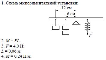
Using a lever, three weights, a tripod and a dynamometer, assemble the setup for studying the balance of the lever. Hang three weights to the left of the axis of rotation of the lever as follows: two weights at a distance of 6 cm and one weight at a distance of 12 cm from the axis. Determine the moment of force that must be applied to the right end of the lever at a distance of 6 cm from the axis of rotation of the lever in order for it to remain in balance in a horizontal position.
On the answer sheet:
1) draw a diagram of the experimental setup;
2) write down the formula for calculating the moment of force;
3) indicate the results of measurements of the applied force and arm length;
4) write down the numerical value of the moment of force.
Determination of the elastic force when lifting a load with a stationary load.
Using a tripod with a clutch, a fixed block, a thread, three weights and a dynamometer, assemble an experimental setup for measuring the work of the elastic force when lifting loads uniformly using a fixed block. Calculate the work done by the elastic force when lifting the load to a height of 20 cm.
On the answer sheet:
1) draw a drawing of the experimental setup;
2) write down the formula for calculating the work of the elastic force;
3) indicate the results of direct measurements of the elastic force and path;
4) write down the numerical value of the work of the elastic force.
PRACTICAL WORKS ON OGE PHYSICS 9 CLASS.
1. Determination of the frequency of free oscillations of a thread pendulum
Using a tripod with a clutch and foot, a weight with a thread attached to it, a meter ruler and a stopwatch, assemble an experimental setup for studying the free oscillations of a thread pendulum. Determine the time of 30 complete oscillations and calculate the oscillation frequency for the case when the length of the thread is 1 m.
On the answer sheet:
2) write down the formula for calculating the oscillation frequency;
4) write down the numerical value of the oscillation frequency of the pendulum.
2. Dependence of the elastic force on the degree of stretching of the spring
Using a tripod with a clutch and foot, a spring, a dynamometer, a ruler and a set of three weights, assemble an experimental setup to study the dependence of the elastic force that occurs in the spring on the degree of stretching of the spring. Determine the tension of the spring by hanging one, two and three weights alternately from it. Use a dynamometer to determine the weight of the loads.
On the answer sheet:
1) draw a drawing of the experimental setup;
2) indicate the results of measuring the weight of the goods and the elongation of the spring for three cases in the form of a table (or graph);
3) formulate a conclusion about the dependence of the elastic force arising in the spring on the degree of stretching of the spring.
Sample possible implementation

3.. Determining the stiffness of the spring
To complete this task, use laboratory equipment: a tripod with a clutch and foot, a spring, a dynamometer, a ruler, and two weights. Assemble an experimental setup to determine the stiffness of the spring. Determine the stiffness of the spring by hanging two weights from it. Use a dynamometer to determine the weight of the loads.
When completing a task:
1) draw a drawing of the experimental setup;
2) write down the formula for calculating the stiffness of the spring;
3) indicate the results of measuring the weight of the weights and the elongation of the spring;
4) write down the numerical value of the spring stiffness.
Example of a possible implementation
4. Dependence of the period of free oscillations of a thread pendulum on the length
Using a tripod with a clutch and foot, a ball with a thread attached to it, a ruler and a clock with a second hand (or a stopwatch), assemble an experimental setup to study the dependence of the period of free oscillations of a thread pendulum on the length of the thread. Determine the time for 30 complete oscillations and calculate the period of oscillation for three cases when the length of the thread is respectively 1 m, 0.5 m and 0.25 m.
On the answer sheet:
1) draw a drawing of the experimental setup;
2) indicate the results of direct measurements of the number of oscillations and the oscillation time for three lengths of the pendulum thread in the form of a table;
3) calculate the oscillation period for each case and enter the results in the table;
4) formulate a qualitative conclusion about the dependence of the period of free oscillations of the thread pendulum on the length of the thread.
Example of a possible implementation
5. Measuring the coefficient of sliding friction
Using a carriage (bar) with a hook, a dynamometer, one weight, a guide rail, assemble an experimental setup to measure the coefficient of sliding friction between the carriage and the surface of the rail.
On the answer sheet:
1) draw a drawing of the experimental setup;
2) write down the formula for calculating the coefficient of sliding friction;
3) indicate the results of measuring the weight of the carriage with the load and the sliding friction force when the carriage with the load moves along the surface of the rail;
4) write down the numerical value of the coefficient of sliding friction.
Example of a possible implementation

6. Dependence of the period of free oscillations of a spring pendulum on the mass of the load
Using a tripod with a clutch and foot, a spring, a set of weights and a stopwatch, assemble an experimental setup for studying the free oscillations of a spring pendulum. Determine the time for 20-30 complete oscillations and calculate the period of oscillation for the weights various masses.
On the answer sheet:
1) draw a drawing of the experimental setup;
2) measure the duration of 20-30 complete oscillations for loads of three different masses, present the results in a table;
3) calculate the oscillation period for each case, round the results to hundredths of a second and enter in the table;
4) formulate a conclusion about the dependence of the period of free oscillations of a spring pendulum on the mass of the load.
Example of a possible implementation

7. Determination of the moment of force applied to the lever
Using a lever, three weights, a tripod and a dynamometer, assemble the setup for studying the balance of the lever. Hang three weights to the left of the axis of rotation of the lever as follows: two weights at a distance of 6 cm and one weight at a distance of 12 cm from the axis. Determine the moment of force that must be applied to the right end of the lever at a distance of 6 cm from the axis of rotation of the lever in order for it to remain in balance in a horizontal position.
On the answer sheet:
1) draw a diagram of the experimental setup;
2) write down the formula for calculating the moment of force;
3) indicate the results of measurements of the applied force and arm length;
4) write down the numerical value of the moment of force.
Example of a possible implementation
8. Density determination
Using a weight balance, a beaker, a glass of water, a cylinder, assemble an experimental setup to measure the density of the material from which the cylinder is made.
On the answer sheet:
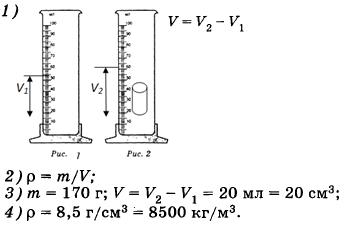
1) draw a drawing of an experimental setup for determining the volume of a body;
2) write down the formula for calculating the density;
3) indicate the results of measuring the mass of the cylinder and its volume;
4) write down the numerical value of the material density of the cylinder.
Example of a possible implementation
9. Buoyancy measurement
Assemble the experimental setup for measuring the buoyancy force.
On the answer sheet:
2) write down the formula for calculating the buoyancy force;
4) write down the numerical value of the buoyancy force.
Example of a possible implementation

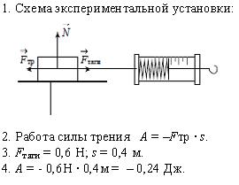
10. Friction force work
Using a carriage (bar) with a hook, a dynamometer, two weights, a guide rail, assemble an experimental setup for measuring the work of the sliding friction force when the carriage with weights moves along the surface of the rail for a distance of 40 cm.
On the answer sheet:
1) draw a drawing of the experimental setup;
2) write down the formula for calculating the work of the sliding friction force;
3) indicate the results of measuring the displacement module of the carriage with loads and the sliding friction force when the carriage with loads moves along the surface of the rail;
4) write down the numerical value of the sliding friction work.
Example of a possible implementation
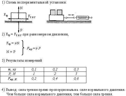
11. Study of the dependence of the sliding friction force on the normal pressure force
Using a carriage (bar) with a hook, a dynamometer, two weights, a guide rail, assemble an experimental setup to study the dependence of the sliding friction force on the normal pressure force.
On the answer sheet:
1) draw the scheme of the experiment;
2) write down the formula for calculating the force of sliding friction;
3) indicate the measurement results;
4) formulate a conclusion about the dependence of the sliding friction force on the force of normal pressure.
Example of a possible implementation
12. Measurement of the period of free oscillations of a thread pendulum
Using a tripod with a clutch and foot, a weight with a thread attached to it, a meter ruler and a stopwatch, assemble an experimental setup for studying the period of free oscillations of a thread pendulum. Determine the time for 30 complete oscillations and calculate the oscillation period for the case when the length of the thread is 1 m.
On the answer sheet:
1) draw a drawing of the experimental setup;
2) write down the formula for calculating the oscillation period;
3) indicate the results of direct measurements of the number of oscillations and the time of oscillations;
4) write down the numerical value of the period of oscillation of the pendulum.
Example of a possible implementation
13. Determination of the work of the elastic force when lifting a load using a fixed block
Using a tripod with a clutch, a fixed block, a thread, three weights and a dynamometer, assemble an experimental setup for measuring the work of the elastic force when lifting loads uniformly using a fixed block. Calculate the work done by the elastic force when lifting the load to a height of 20 cm.
On the answer sheet:
1) draw a drawing of the experimental setup;
2) write down the formula for calculating the work of the elastic force;
3) indicate the results of direct measurements of the elastic force and path;
4) write down the numerical value of the work of the elastic force.
Example of a possible implementation

14. Determination of the optical power of the lens
Using a converging lens, a screen, a ruler, assemble an experimental setup to determine the optical power of the lens. Use light from a distant window as the light source.
On the answer sheet:
1) draw a drawing of the experimental setup;
2) write down the formula for calculating the optical power of the lens;
3) indicate the result of measuring the focal length of the lens;
4) write down the numerical value of the optical power of the lens.
Example of a possible implementation

15. Voltage when two conductors are connected in series
Using a current source (4.5 V), voltmeter, key, connecting wires, resistors marked R 1 and R 2 , check experimentally the rule for electric voltage when two conductors are connected in series.
On the answer sheet:
2) measure the voltage at the ends of each of the resistors and the total voltage at the ends of the circuit of two resistors when they are connected in series;
3) compare the total voltage across the two resistors with the sum of the voltages across each of the resistors, given that the error of direct measurements with a laboratory voltmeter is 0.2 V.
Make a conclusion about the validity or fallacy of the rule being tested.
Example of a possible implementation

16. Dependence of the voltage at the ends of the conductor on the strength of the electric current
Using a current source (4.5 V), voltmeter, ammeter, key, rheostat, connecting wires, resistor marked R 1 , assemble an experimental setup to study the dependence of the electric current in the resistor on the voltage at its ends.
On the answer sheet:
Example of a possible implementation

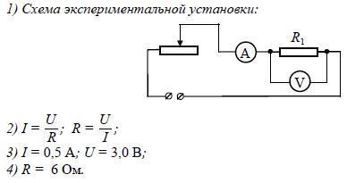
17. Determination of the electrical resistance of a resistor
For this task, use laboratory equipment: current source (4.5 V), voltmeter, ammeter, key, rheostat, connecting wires, resistor marked R 1 . Assemble an experimental setup to determine the electrical resistance of a resistor. Using a rheostat, set the current in the circuit to 0.5 A.
On the answer sheet:
1) draw the electrical circuit of the experiment;
2) write down the formula for calculating electrical resistance;
4) write down the numerical value of the electrical resistance.
Example of a possible implementation
18. Study of the dependence of the strength of the electric current in the resistor on the voltage at its ends
Using a current source (4.5 V), a voltmeter, an ammeter, a key, a rheostat, connecting wires, a resistor, assemble an experimental setup to study the dependence of the electric current in the resistor on the voltage at its ends.
On the answer sheet:
1) draw the electrical circuit of the experiment;
2) using a rheostat, setting in turn the current strength in the circuit 0.4 A, 0.5 A and 0.6 A and measuring in each case the values of the electrical voltage at the ends of the resistor, indicate the results of measuring the current strength and voltage for three cases in the form of a table (or graphics);
3) formulate a conclusion about the dependence of the electric current in the resistor on the voltage at its ends.
Example of a possible implementation
19. Determination of the power of electric current
Using a current source (4.5 V), a voltmeter, an ammeter, a key, a rheostat, connecting wires, a resistor, assemble an experimental setup to determine the power dissipated in the resistor. Using a rheostat, set the current in the circuit to 0.5 A.
On the answer sheet:
1) draw the electrical circuit of the experiment;
2) write down the formula for calculating the power of electric current;
3) indicate the results of voltage measurement at a current strength of 0.5 A;
4) write down the numerical value of the power of the electric current.
Example of a possible implementation
20. Current strength with parallel connection of two conductors
Using a current source (4.5 V), an ammeter, a key, connecting wires, resistors marked R1 and R2, check experimentally the rule for electric voltage when two conductors are connected in series.
On the answer sheet:
1) draw the electrical circuit of the experimental setup;
2) measure the current strength on each of the resistors and the total current strength in the circuit when they are connected in parallel;
3) compare the total current in the circuit with the sum of the currents on each of the resistors, given that the error of direct measurements using a laboratory ammeter is 0.05 A. Make a conclusion about the validity or fallacy of the rule being tested.
Sample possible solution
21. Determination of the work of electric current
To complete this task, use laboratory equipment: a current source (4.5 V), a voltmeter, an ammeter, a key, a rheostat, connecting wires, a resistor R. Assemble an experimental setup for measuring the work of an electric current. Using a rheostat, set the current in the circuit to 0.5 A.
On the answer sheet:
1) draw the electrical circuit of the experiment;
2) write down the formula for calculating the work of an electric current;
3) indicate the results of voltage measurement at a current strength of 0.5 A for 10 minutes;
4) write down the numerical value of the work of the electric current.
Example of a possible implementation

PRACTICAL PART OGE PHYSICS 9
-
Suggested works: Definition
Purpose of the assignment
Suggested works: Study
Objective
Suggested works : Examination
Experimental tasks of the 1st type
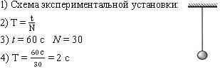
Determination of the period and frequency of oscillation of a mathematical pendulum
Use set №7
To complete this task, use laboratory equipment: a tripod with a clutch and foot; meter ruler (error 5 mm); a ball with a thread attached to it; clock with a second hand (or stopwatch). Assemble an experimental setup to determine the period and frequency of free oscillations of a thread pendulum.
On the answer sheet:
1. make a drawing of the experimental setup;
2. Give a formula for calculating the period and frequency of oscillations;
3. indicate the results of direct measurements of the number of oscillations and the time of oscillations for pendulum thread lengths
equal to 0.5 m;
calculate the period and frequency.
Example of a possible solution
2) T = t/N; v = 1/T;
3) N = 30; t = 42 s.
4) T \u003d t / N \u003d 1.4 s; ν \u003d 1 / T \u003d 0.7 Hz.
Conclusion: During the execution of the experimental task, the period of free oscillations turned out to be 1.4 s,
frequency 0.7 Hz.
Determination of the moment of force acting on the lever
Use set №8
Using a lever, three weights, a tripod and a dynamometer, assemble the setup for studying the balance of the lever. Hang three weights to the left of the axis of rotation of the lever as follows: two weights at a distance of 6 cm and one weight at a distance of 12 cm from the axis. Determine the moment of force that must be applied to the right end of the lever at a distance of 12 cm from the axis of rotation of the lever in order for it to remain in balance in a horizontal position.
On the answer sheet:
1. draw a diagram of the experimental setup;
2. write down the formula for calculating the moment of force;
3. indicate the results of measurements of the applied force and arm length;
4. Write down the numerical value of the moment of force.
Example of a possible solution: 1) Scheme of the experimental setup:

3) F = 2H, l = 0.12 m
4) M = 2H · 0.12 m = 0.3 N · m
Conclusion: During the execution of the experimental task, the moment of force that must be applied to
the right end of the lever turned out to be equal to 0.3 N m.
Example of a possible solution
1 ) Scheme of the experimental setup:
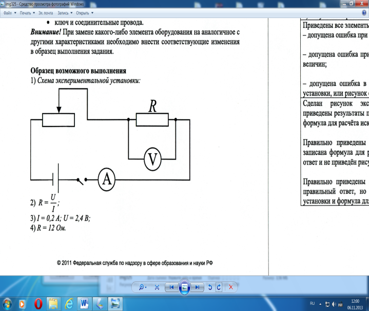

Conclusion: During the experiment. setting the resistance of the resistor R 1 turned out to be 12 ohms.
Determining the work of the current
Use set №5
Using a current source, voltmeter, ammeter, key, rheostat, connecting wires, resistor marked R, assemble an experimental setup to determine the work of an electric current on a resistor. Using a rheostat, set the current in the circuit to 0.3 A. Determine the work of the electric current in 10 minutes.
On the answer sheet:
2. write down the formula for calculating the work of an electric current;
3. Indicate the results of voltage measurement at a current strength of 0.3 A;
4. Write down the numerical value of the work of the electric current.
Example of a possible solution
1) Scheme of the experimental setup:
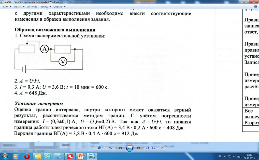


Conclusion: During the execution of the experimental task, the current work turned out to be equal to 648 J .
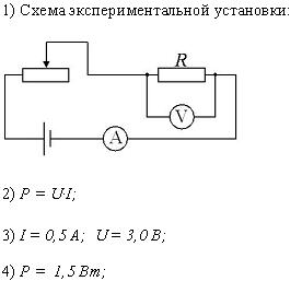
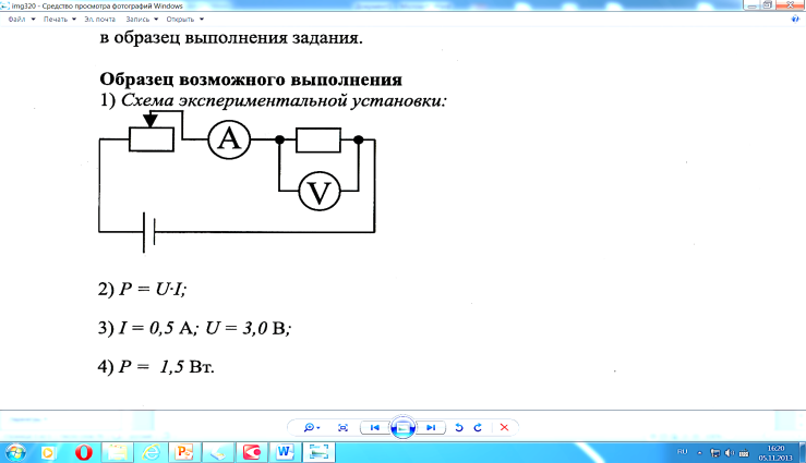
Determination of current power
Use set №5
Using a current source (4.5 V), a voltmeter, an ammeter, a key, a rheostat, connecting wires, resistor marked R2 , assemble an experimental setup to determine the power dissipated in a resistor at current strength 0.5 A.
On the answer sheet:
1.draw the electrical circuit of the experiment;
2. write down the formula for calculating the power of electric current;
3. Indicate the results of voltage measurement at a current strength of 0.5 A;
4. Write down the numerical value of the power of the electric current.
Example of a possible solution
1) Scheme of the experimental setup:


Conclusion: During the experiment. setting the power of the electric current was equal to 1.5 watts.
Experimental tasks of the 2nd type
Example of a possible solution
1) Scheme of the experimental setup:
3.Conclusion: During the execution of the experimental task, it turned out that with a decrease in the length of the thread
the period of free oscillations decreases.
Example of a possible solution
1) Scheme of the experimental setup:
4)Conclusion: The total voltage across two series-connected resistors is equal to the sum of the voltages
on each of the resistors.
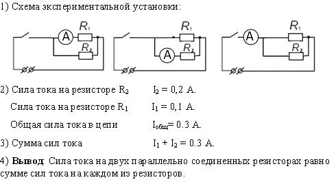
Example of a possible solution
1) Scheme of the experimental setup:
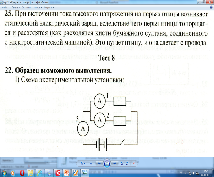
| I, A | I 1 , A | I 2 , A | Conclusion |
| 0,6 | 0,4 | 0,2 | I \u003d I 1 + I 2 |
4)Conclusion: During the execution of the experimental task, it turned out that the current strength on the main conductor is equal to the sum of the current strengths in parallel-connected conductors.
Preparation of the practical part of the OGE in physics
Experimental tasks #23
Experimental skills are tested with three types of tasks:
- assignments for indirect measurements physical quantities;
Tasks that test the ability to present experimental results in the form of tables or
graphs and draw conclusions based on the experimental data obtained;
Tasks that test the ability to conduct an experimental verification of physical laws;
List of equipment sets:
Experimental tasks of the 1st type
The purpose of the task: testing the ability to conduct indirect measurements of physical quantities.
Suggested works: Definition
5. period and frequency of oscillation of a mathematical pendulum,
6. moment of force acting on the lever,
7. the work of the elastic force when lifting the load using a movable or fixed block,
10.electric resistance resistor,
11.Electric current work,
12. power of electric current.
Experimental tasks of the 2nd type
Purpose of the assignment: testing the ability to present experimental results in the form of tables or graphs and draw conclusions based on the experimental data obtained.
Suggested works: Study
3.dependence of the period of oscillation of the mathematical pendulum on the length of the thread,
4.dependence of the current strength arising in the conductor, on the voltage at the ends of the conductor,
Experimental tasks of the 3rd type
Objective: testing the ability to conduct an experimental verification of physical laws and consequences.
Suggested works : Examination
1. The law of series connection of resistors for electrical voltage
2. The law of parallel connection of resistors for the strength of electric current
Experimental tasks of the 1st type


