Frequency of radio emission. Radio waves and their propagation
Radio waves are a type of electromagnetic waves, the existence of which was predicted in 1864 by the British physicist, mathematician and mechanic James Clerk Maxwell, the author of the electromagnetic field theory.
Maxwell's theory
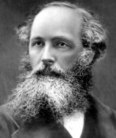
James Clerk Maxwell
Summarizing the results of studies carried out before him in the field of electric and magnetic fields, Maxwell suggested that alternating magnetic fields generate electric fields, and alternating electric fields generate magnetic fields, etc. First, one of these fields is created by some external source, and then, causing each other to appear, they seem to break away from the original source and exist independently of it, propagating further in space in the form of electromagnetic waves.
Unfortunately, the famous scientist was not destined to experimentally confirm his brilliant theory, which combined the description of all the phenomena of electricity and magnetism. This was done later by another scientist.
Hertz experience
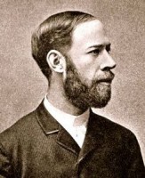
Heinrich Rudolf Hertz
For the first time in practice, the existence of electromagnetic waves was proved in 1887 by the German physicist Heinrich Rudolf Hertz, who at that time worked as a professor of physics technical university in Karlsruhe. It should be said that Hertz undertook this experiment not at all because he agreed with Maxwell. On the contrary, he assumed that Maxwell was mistaken and that there are no electromagnetic waves in reality. This is what he wanted to prove.
According to Maxwell's theory, the source of electromagnetic waves can be oscillating electrical particles. For this purpose, the simplest oscillatory circuit is used, consisting of a capacitor and an inductor.
The emitter of electromagnetic waves (if they exist) in Hertz's first experiment was to be an electric discharge arising between two brass balls fixed at the ends of metal rods. In the experimental setup, the balls, which acted as a capacitor, were separated by a small gap, and the rods themselves were interconnected by an inductor. Electric charges accumulated in the balls.
At a distance of several meters from the first circuit, the second circuit was located, not connected to the first one and representing an open wire ring with the same brass balls at the ends and with the same spark gap as in the first circuit. It was the simplest resonator - a device for capturing electromagnetic waves.
At some point, sparks jumped between the balls of the primary circuit. And if there are no electromagnetic waves in nature, there should be no discharge in the second circuit. But during the experiment, such a discharge also appeared between the balls of the second circuit. This meant that electromagnetic waves still exist. And their energy can be transmitted wirelessly.
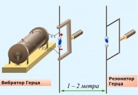
Hertz's experiment on the detection of electromagnetic waves
Hertz conducted a series of experiments that confirmed Maxwell's theory. He found that the speed of propagation of electromagnetic waves in vacuum is equal to the speed of light. Moreover, by examining the propagation of these waves, he proved that they behave in the same way as the waves of light and obey the laws of reflection and refraction.
But he had no idea how it could be put into practice. And he considered his discoveries absolutely useless. "Maestro Maxwell was right," Hertz told the students. "Electromagnetic waves exist, but we cannot see them with our eyes." And to the question "What's next?" he replied, "Nothing, I suppose."
In the scientific community, the discovery of Hertz was called the beginning of a new "electric era".
Subsequently, a range of radio waves was isolated from the entire spectrum of electromagnetic waves, which began to be used for the transmission of radio signals.
Radio wave range
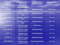
Radio Wave Band Table
All electromagnetic waves propagate in vacuum at a speed equal to the speed of light. They differ in wavelength or frequency. There is no sharp boundary between them. One kind of electromagnetic waves smoothly passes into another.
Depending on the wavelength, the entire spectrum of electromagnetic waves is conventionally divided into gamma radiation, x-rays, visible light, infrared radiation and radio waves.
The shortest wavelength, only 2·10 −10 m, has gamma radiation. All electromagnetic waves whose length exceeds the wavelength of infrared light and is in the range from 1 mm to 100 km are radio waves. These are electromagnetic waves that are used in radio engineering. Their frequency fluctuates in the range of 3 kHz - 300 GHz.
According to international agreements, the entire spectrum of radio waves is divided into the following ranges: decimeter, millimeter, centimeter, decimeter, meter, decameter, hectometer, kilometer, myriameter.
millimeter waves
Waves having a length of 1 mm to 1 cm are called millimeter. Their frequency is in the range from 30 to 300 GHz and is called extremely high(EHF). Such waves are used in radar, space communications, and radio astronomy.
The spectrum of radio waves used for broadcasting is usually divided into ultrashort, short, medium, long and extra long waves.
ultrashort waves
To ultrashort include centimeter, decimeter and meter waves.
Wavelengths from 1 cm to 10 cm and frequencies from 3 to 30 GHz ( ultra high frequencies EHF) are called centimeter. This range is used to transmit data over the air in satellite communication channels, wireless computer networks Wi-Fi, in radar and radio communications.
Waves with a wavelength in the range from 10 cm to 1 m, a frequency of 300-3000 MHz are called decimeter, and their frequency ultra high frequency(UHF). They are used in radio communications, television, walkie-talkies, mobile phones, microwave ovens.
Waves whose length ranges from 1 m to 10 m are called meter. Most often they are used for radio communications, television and radio broadcasting over a short distance.
short waves
Short waves are waves in the range from 10 to 100 m. They are called decameter waves.
medium waves
medium, or hectometric, waves occupy a range from 100 m to 1 km.
Long waves
Long, or kilometer, waves are in the range from 1 km to 10 km.
Short, medium, and long wave radio waves are used in broadcasting and radio communications.
Ultra long waves
All radio waves longer than 10 km are called extra long. They are divided into myriameter (wavelength from 10 km to 100 km), hectokilometer (in the range from 100 km to 1000 km), megameter (from 1000 km to 10,000 km) and deca-megameter (from 10,000 km to 100,000 km).
Extra long radio waves are used to communicate with submarines.
decimm waves
Separately, it must be said about ecimillimeter waves. Such wavelengths are considered to be between 0.1 mm and 1 mm. They are also called submillimeter. It's kind electromagnetic radiation, the frequency spectrum of which is located between infrared and microwave radiation, including the range of decimeter, centimeter and millimeter radio waves. Although according to the international classification it belongs to radio waves, it is used mainly in medicine and security systems. Unlike X-ray, it is safe for the human body, therefore it is used in devices for scanning organs. human body. At airports, it is used to “shine through” the baggage of passengers. In physics, it is called terahertz radiation due to its high frequency, located in the range of 10 11 -10 13 Hz.
Radio range estimation:
1. Superlong waves - SLW> 1000 km;
2. Long waves - LW=1000km;
3. Medium waves - SW=400km;
4. Short, waves - KV=20000km;
5. Ultrashort waves - VHF = 70 km.
The ionosphere is a reflective layer for long, medium and partially short waves. Possessing good diffraction ability, radio waves of these ranges (especially VLF and LW) can overcome considerable distances. These ranges are used for international broadcasting, navigation.
HF signals in most affected by industrial interference, interference from household appliances, broadcasting and television transmitters. The use of equipment of this range is optimal in rural areas, where the level of interference is much lower than in dense urban areas. The range is characterized by good enveloping of uneven terrain and propagation beyond the line of sight. Good results in terms of communication range are obtained between stationary objects. Car and portable radio stations have a shorter communication range due to the low efficiency of the antennas, since the wavelength is much longer than the antenna length.
The VHF band is one of the most versatile bands. The equipment of this range works perfectly both in rural areas and in urban areas. Ultrashort waves pass through the ionosphere almost unhindered, so it is believed that VHF radio communication is carried out by a surface wave within the line of sight, because. these waves almost do not have the property of diffraction.
For the same reason, behind some separate obstacles, radio shadow zones, when there is a whole complex of them (urban area), then radio communication in the radio shadow zone is carried out due to the arrival of waves that are repeatedly reflected from the structures standing next to the subscriber. Because Since this range of radio waves has insufficient over-the-horizon propagation, then to increase the radio communication range, a large installation height of the radio base station antenna is required. Portable stations operate quite successfully in open areas, but in dense urban areas, the quality of communication is significantly reduced. The efficiency of helical antennas is quite high, but, nevertheless, not the maximum due to the difference in wavelength and geometric dimensions of the antennas. In the general case, the stable communication range of a surface wave is about 70 km. The VHF communication range increases due to refraction, refraction of radio waves in the lower layers of the atmosphere due to the heterogeneity of the layers, as well as due to the appearance in the ionosphere of an area with increased ionization, which most often manifest themselves during the period of solar activity.
The UHF range is considered "urban" and shows its own best qualities in dense urban areas. The choice of this range is optimal when it is necessary to obtain a stable connection over short distances, for example, within the city. Even when using portable radios, a stable connection is provided with a minimum number of "dead" zones. For open areas, the UHF is not very convenient, since the radio waves of this range do not go around uneven terrain well and have strong attenuation in wooded areas. To obtain a long range of communication, very high points of installation of antennas of base stations will be required.
Centimeter waves are most often used to organize space communications, due to the good radio wave penetration of this range of ionospheric layers. Higher frequency bands of radio waves have not yet been mastered for use.
In the activities of fire and rescue units for organizing radio communications, VHF radio waves have found the greatest use, and the HF band is less commonly used. The main advantages of VHF communications are that communication in this range is more stable and practically does not depend on the time of day and weather, in this range there is a relatively low level of industrial interference, and the characteristics of VHF propagation make it possible to use the same frequencies in neighboring garrisons. VHF antenna devices have much smaller dimensions than HF communication antennas, and even more so MW and LW antennas, which is important for organizing radio communications in urban environments.
The zone of stable radio communication in the VHF range depends on many factors, and due to the fact that the specifics of the activity of fire and rescue units involve the organization of radio communication, as a rule, in urban conditions, the communication range in some cases turns out to be significantly less than that indicated in Figure 3.8. It is necessary to choose the right places for working with radio stations.


Rice. 3.8. Approximate range of VHF radio communication
between different types of radio
Factors affecting the range of VHF communication:
1) Transmitter power, W.
2) Receiver sensitivity, μV.
3) Depth of noise reduction.
4) Terrain.
5) Lift height and antenna design.
6) Industrial interference, electrical installations of power lines.
7) Obstacles and shielding structures, stone and reinforced concrete buildings, metal structures.
Advantages of VHF: does not depend on the time of day, many radio channels, the operation of areas at the same frequencies.
Shortwave communications are used to communicate with remote units at a distance of over 50 km. The effectiveness of HF radio communications is especially evident in garrisons with a large territory and a significant distance between units from each other (Siberia, Far East, northern European part). In some cases, a greater effect than HF communication is achieved by using the centimeter wave range used in satellite radio communication systems.
For the organization of administrative communications, the decimeter wave range is now increasingly used. For these purposes, in most cases, it is currently more efficient to use a fairly large and rapidly developing infrastructure of communication networks of general purpose mobile service providers (cellular systems). Modern professional radio communication systems (trunking systems) can be effectively used to solve service problems. For the organization of departmental networks of land mobile radio communications in the territory Russian Federation for the operation of various services, the frequency ranges indicated in Table 3.2 are allocated. Permission to use radio frequencies is issued by the divisions of the radio frequency service, and the legality of their use is within the competence of communications supervision. Both structures are state organizations that regulate the communications industry. In general, there is currently a tendency to use radio waves of a higher frequency range, where there is practically no industrial interference and the problems associated with the lack of a frequency range for organizing radio communications are significantly reduced.
HF (short wave) is a spectrum of radio frequencies covering the interval from 1.6 to 30 MHz. Within this frequency spectrum, the most efficient form of modulation is SSB (Single Sideband Partially Suppressed Carrier). This type modulation together with the use of the ionosphere - a layer of ionized gases at a distance of 100 - 700 km from the earth's surface, provides the most efficient radio communication over both short and medium, and long distances. In this case, there is no need to use expensive relay devices, such as VHF repeaters or satellites, which dramatically increase the “cost” of radio communications and complicate its physical infrastructure.
In most remote areas, the only possible mode of radio communication is SSB on HF.
Passage on KV
When the transceiver generates HF/SSB radio waves, they are divided into two components:
- A sky wave that travels across the earth's surface from a transmitting antenna to a receiving antenna.
- The reflected wave, which is radiated at some angle from the antenna, reaches the ionosphere (a layer of ionized gases above the earth's surface) and is reflected from it back to the earth to the receiving antenna.
In general, sky wave is used for communication over short distances up to 50 km. As a sky wave curves around the surface of the earth, its propagation is affected by the type of soil over which it passes. The level of a sky wave decreases quite sharply when it propagates over forests and mountainous areas.
The reflected wave is used to establish radio communications over medium and long distances up to 3000 km. Due to its nature, the propagation of the reflected wave does not depend on the type of soil, however, it depends on the factors affecting the ionosphere.
Schemes of the passage of radio waves
The figures below show the characteristics of sky and reflected waves during the day and at night. In each case, the height of the ionosphere is shown schematically
In both figures, station A establishes radio links with stations B, C, D. Radio communication between stations A and B is carried out using a sky wave. The figure shows that the connection between these stations does not depend on the time of day and the height of the ionosphere above the earth.
Communication between stations A and C, D is provided by the reflected wave, and therefore depends on the time of day and the height of the ionosphere above the earth.
Recommendations for choosing the operating frequency are given under each figure. Please note that this information may vary depending on the time of year and other factors. These examples are given as general provisions and may differ significantly in practice.
Day
Since the sun is high, the ionospheric layer is also high - it is recommended to use a higher frequency section of the HF:
A - C Optimum operating frequency within 7-9 MHz
A - D Optimum operating frequency within 13-16 MHz
Night
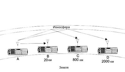
Since the sun is low, the ionospheric layer is also low - it is recommended to use a lower frequency section of the HF:
A - B Optimum operating frequency 3 MHz
A - C Optimum operating frequency within 5-7 MHz
A - D Optimum operating frequency within 9-12 MHz
Factors affecting the quality of HF/SSB communication
There are a number of different factors that affect the quality of HF/SSB radio communications. They are listed below:
Frequency selection
The choice of frequency is the most important factor for successful radio communications in the HF band. In general, the more distance you need to cover, the higher frequencies you need to use.
Times of Day
There is a rule, the higher the sun, the higher the frequency must be used. This means that if you normally use low frequencies for radio communication in the early morning, late afternoon and evening, for example, you will need to use a higher frequency to cover the same distances at noon. This rule must be observed very carefully, especially if your transceiver contains a limited number of operating frequencies, and therefore effective radio communication is possible only at certain times of the day.
Weather
Weather conditions also affect the quality of HF/SSB radio communications. When a storm approaches your location, the noise of the aether increases dramatically as a result of static lightning discharges. In this case, the air noise may increase to such a level that reception of the desired signals will not be possible.
Electrical interference
Electrical interference can be caused by overloaded power lines, heavy duty generators, air conditioners, thermostats, refrigerators, and car engines if they are located very close to your antenna. As a result of the operation of such devices in the transceiver, the noise level of the air can sharply increase.
System layout and installation
The method by which your system is configured and installed also affects the quality of the radio. The choice of antenna and power source is extremely critical. Correct installation is also important. Setting up a transceiver for HF/SSB operation is very different from setting up transceivers for VHF operation. The quality of radio communication in the future depends on how accurately you follow all the instructions for installing the transceiver and antennas.
additional information
Radio communication using an SSB transceiver on HF will be different from using any station on VHF or microwave. This is due to the difference in the nature of HF radio communications and the use various kinds modulation. When using SSB on HF, you will always hear some noise in the background of the received signal, and the level of this noise may vary depending on electrical interference and storm activity in your area.
Radio waves, and their distribution, are an undeniable mystery for beginners on the air. Here you can get acquainted with the basics of the theory of propagation of radio waves. This article is intended to introduce novice fans of the air, as well as for those who have some idea about it.
The most important introductory, which is often forgotten to be said before introducing the theory of radio wave propagation, is that radio waves propagate around our planet due to reflection from the ionosphere and a beam of light is reflected from the earth as from translucent mirrors.
Peculiarities of medium wave propagation and cross modulation
Medium waves include radio waves with a length of 1000 to 100 m (frequency 0.3 - 3.0 MHz). Medium waves are mainly used for broadcasting. And they are also the cradle of domestic radio piracy. They can spread terrestrial and ionospheric way. Medium waves experience significant absorption in the semiconducting surface of the Earth, the range of propagation of the earth wave 1, (see Fig. 1), is limited to a distance of 500-700 km. Over long distances, radio waves 2 and 3 are propagated by an ionospheric (spatial) wave.
At night, medium waves propagate by reflection from the E layer of the ionosphere (see Fig. 2), the electron density of which is sufficient for this. In the daytime, on the path of wave propagation, layer D is located, which extremely strongly absorbs medium waves. Therefore, at ordinary transmitter powers, the intensity electric field is insufficient for reception, and in the daytime the propagation of medium waves occurs practically only by the ground wave over relatively short distances, on the order of 1000 km. In the medium wave range, the longer waves experience less absorption and the electric field strength of the skywave is greater at longer wavelengths. Absorption increases in summer months and decreases in winter. Ionospheric disturbances do not affect the propagation of medium waves, since the E layer is little disturbed during ionospheric-magnetic storms.
At night, see fig. 1, at some distance from the transmitter (point B), the simultaneous arrival of spatial 3 and surface waves 1 is possible, and the length of the path of the spatial wave varies with the change in the electron density of the ionosphere. A change in the phase difference of these waves leads to fluctuations in the electric field strength, called near field fading.
At a considerable distance from the transmitter (point C), waves 2 and 3 can arrive by one or two reflections from the ionosphere. A change in the phase difference of these two waves also results in a fluctuation in the electric field strength, called far field fading.
To combat fading at the transmitting end of the communication line, antennas are used, in which the maximum of the radiation pattern is “pressed” to earth's surface, these include the simplest antenna "Inverted-V", quite often used by radio amateurs. With such a radiation pattern, the zone of near fading moves away from the transmitter, and at large distances the field of the wave that arrived by way of two reflections is weakened.
Unfortunately, not all novice broadcasters operating in the 1600-3000 kHz frequency range are aware that a weak signal from a low-power transmitter is subject to ionospheric distortion. The signal from more powerful radio transmitters is less susceptible to ionospheric distortion. Due to the nonlinear ionization of the ionosphere, a weak signal is modulated by the modulating voltage of the signals from powerful stations. This phenomenon is called cross modulation. The depth of the modulation coefficient reaches 5-8%. From the reception side, the impression is made of a poorly executed transmitter, with all sorts of hums and wheezing, this is especially noticeable in the AM modulation mode.
Due to cross modulation, intense lightning noise often penetrates the receiver, which cannot be filtered out - the lightning discharge modulates the received signal. It is for this reason that broadcasters began to use single-sideband transmitters for two-way radio communications and began to operate more often at higher frequencies. Foreign radio transmitters of CB stations amplify them and compress modulating signals, and for undistorted operation on the air, they use inverse frequencies.
The phenomena of demodulation and cross modulation in the ionosphere are observed only in the range of medium waves (MW). In the short wave (SW) range, the speed of an electron under the action of an electric field is negligible compared to its thermal speed, and the presence of a field does not change the number of collisions of an electron with heavy particles.
The most favorable, in the frequency range from 1500 to 3000 kHz for long-distance communications, are winter nights and periods of minimum solar activity. Extra long distance connections, over 10,000 km, are usually possible at sunset and sunrise. In the daytime, communication is possible at a distance of up to 300 km. Free FM radio broadcasters can only envy such large radio routes.
AT summer time interference from static discharges in the atmosphere often interferes on this band.
Features of the propagation of short waves and their characteristics
Short waves include radio waves with a length of 100 to 10 m (frequency 3-30 MHz). The advantage of short wavelength operation over longer wavelength operation is that directional antennas can be easily created in this range. Short waves can propagate as terrestrial, in the low-frequency part of the range, and as ionospheric.
With increasing frequency, the absorption of waves in the semiconducting surface of the Earth increases greatly. Therefore, at ordinary transmitter powers, short-wave terrestrial waves propagate over distances not exceeding several tens of kilometers. On the sea surface, this distance increases significantly.
Short waves can be propagated by an ionospheric wave over many thousands of kilometers, and this does not require high-power transmitters. Therefore, at present, short waves are mainly used for communication and broadcasting over long distances.
Short waves propagate over long distances by reflection from the ionosphere and the Earth's surface. This method of propagation is called hopping, see fig. 2 and is characterized by hop distance, number of hops, exit and arrival angles, maximum usable frequency (MUF), and lowest usable frequency (LFF).
If the ionosphere is uniform in the horizontal direction, then the wave trajectory is also symmetrical. Usually, radiation occurs in a certain range of angles, since the width of the radiation pattern of short-wave antennas in the vertical plane is 10-15 °. The minimum jump distance for which the reflection condition is satisfied is called the silence zone distance (ZM). To reflect the wave, it is necessary that the operating frequency is not higher than the value of the maximum usable frequency (MUF), which is the upper limit of the operating range for given distance. Wave 4.
The use of anti-aircraft radiation antennas, as one of the methods for reducing the silence zone, is limited by the concept of the maximum applicable frequency (MUF), taking into account its reduction by 15-20% of the MUF. Anti-aircraft radiation antennas are used for broadcasting in the near zone by the method of single-hop reflection from the ionosphere.
The second condition limits the operating range from below: the lower the operating frequency (within the shortwave range), the stronger the absorption of the wave in the ionosphere. The lowest applicable frequency (LFC) is determined from the condition that at a transmitter power of 1 kW, the electric field strength of the signal must exceed the noise level, and therefore, the signal absorption in the ionospheric layers should not be more than permissible. The electron density of the ionosphere varies during the day, during the year, and during the period of solar activity. This means that the boundaries of the operating range also change, which leads to the need to change the operating wavelength during the day.
Frequency range 1.5-3 MHz, is nocturnal. It is clear that for a successful radio communication session, you need to choose the right frequency (wavelength) every time, besides, this complicates the design of the station, but for a true connoisseur of long-distance communications, this is not a difficulty, it is part of a hobby. Let's evaluate the HF range by sections.
Frequency range 5-8 MHz, in many ways similar to the 3 MHz band, and unlike it, here in the daytime you can communicate up to 2000 km, the zone of silence (ZM) is absent and is several tens of kilometers. At night, communication is possible over any distance, with the exception of ZM, which increases to several hundred kilometers. During the hours of changing the time of day (sunset/sunrise), the most convenient for long-distance communications. Atmospheric noise is less pronounced than in the range of 1.5-3 MHz.
In the frequency range 10-15 MHz during periods of solar activity, communications are possible during the daytime with almost any point the globe. In summer, the duration of radio communications in this frequency range is round-the-clock, with the exception of certain days. The zone of silence at night has distances of 1500-2000 km and therefore only long-distance communications are possible. In the daytime, they decrease to 400-1000 km.
Frequency range 27-30 MHz Suitable for communication only during daylight hours. This is the most capricious range. It usually opens for several hours, days or weeks, especially when the seasons change, i.e. autumn and spring. The zone of silence (ZM) reaches 2000-2500 km. This phenomenon belongs to the topic of MUF, here the angle of the reflected wave must be small with respect to the ionosphere, otherwise it has a large attenuation in the ionosphere, or a simple escape into space. Small radiation angles correspond to large jumps and correspondingly large silence zones. During periods of maximum solar activity, communication is also possible at night.
In addition to the above models, cases of anomalous propagation of radio waves are possible. Anomalous propagation can occur when a sporadic layer appears on the path of a wave, from which shorter waves, up to meter wavelengths, can be reflected. This phenomenon can be observed in practice by passing distant TV stations and FM radio stations. The MUF of the radio signal during these hours reaches 60-100 MHz during the years of solar activity.
In the VHF FM band, Except in rare cases of anomalous radio wave propagation, propagation is strictly due to the so-called "line of sight". The propagation of radio waves within the line of sight speaks for itself, and is due to the height of the transmitting and receiving antennas. It is clear that in the conditions of urban development it is impossible to speak of any visual and line of sight, but radio waves pass through urban development with some attenuation. The higher the frequency, the higher the attenuation in urban areas. The frequency range 88-108 MHz is also subject to some attenuation in urban conditions.
Fading of HF radio signals
The reception of short radio waves is always accompanied by a measurement of the level of the received signal, and this change is random and temporary. This phenomenon is called fading (fading) of the radio signal. On the air, fast and slow signal fading is observed. The fading depth can reach up to several tens of decibels.
The main cause of fast signal fading is multipath propagation of radio waves. In this case, the cause of fading is the arrival at the receiving point of two beams propagating by one and two reflections from the ionosphere, wave 1 and wave 3, see Fig. 2.
Since the rays travel different paths in distance, their phases of arrival are not the same. Changes in the electron density, continuously occurring in the ionosphere, lead to a change in the path length of each of the rays, and, consequently, to a change in the phase difference between the rays. To change the phase of a wave by 180°, it is enough that the path length changes by only ½. It should be recalled that when rays of one signal arrive at the receiving point with the same strength and with a phase difference of 180 °, they are completely subtracted according to the vector law, and the strength of the incoming signal in this case can be equal to zero. Such small changes in path length can occur continuously, therefore, fluctuations in the electric field strength in the short wave range are frequent and deep. The interval of their observation in 3-7 minutes can be at low frequencies of the HF band, and up to 0.5 seconds at frequencies closer to 30 MHz.
In addition, signal fading is caused by the scattering of radio waves on the inhomogeneities of the ionosphere and the interference of scattered waves.
In addition to interference fading, at short wavelengths, polarization fading occurs. The cause of polarization fading is the rotation of the polarization plane of the wave relative to the received antenna. This occurs when the wave propagates in the direction lines of force magnetic field Earth, and with a change in the electron density of the ionosphere. If the transmitting and receiving antennas are horizontal vibrators, then the radiated horizontally polarized wave, after passing through the ionosphere, will undergo a rotation of the polarization plane. This leads to fluctuations. d.s., induced in the antenna, which has an additional attenuation of up to 10 dB.
In practice, all these causes of signal fading act, as a rule, in a complex manner and obey the described Rayleigh distribution law.
In addition to fast fading, slow fading is observed, which are observed with a period of 40-60 minutes in the low-frequency part of the HF band. The reason for these fading is a change in the absorption of radio waves in the ionosphere. The distribution of the envelope amplitude of the signal during slow fading obeys a normally logarithmic law with a decrease in the signal to 8-12 dB.
To combat fading, on short waves, the antenna diversity method is used. The fact is that the increase and decrease in the strength of the electric field do not occur simultaneously, even on a relatively small area of the earth's surface. In the practice of shortwave communication, usually two antennas are used, spaced apart by several wavelengths, and the signals are added after detection. It is effective to separate antennas by polarization, i.e., simultaneous reception on vertical and horizontal antennas with subsequent addition of signals after detection.
I would like to note that these control measures are effective only for eliminating fast fading, slow signal changes are not eliminated, since this is due to a change in the absorption of radio waves in the ionosphere.
In amateur radio practice, the antenna diversity method is used quite rarely, due to the constructive high cost and the lack of the need to receive sufficiently reliable information. This is due to the fact that amateurs often use resonant and band antennas, the number of which in his household is about 2-3 pieces. The use of diversity reception requires an increase in the number of antennas at least twice.
Another thing is when an amateur lives in a rural area, while having enough space to accommodate an anti-fading structure, he can simply use two broadband vibrators for this, covering all, or almost all, of the required ranges. One vibrator must be vertical, the other horizontal. It is not necessary to have several masts for this. It is enough to place them on the same mast so that they are oriented relative to each other at an angle of 90 °. The two antennas, in this case, will resemble the well-known "Inverted-V" antenna.
Calculation of the radius of coverage by a radio signal in the VHF / FM bands
The frequencies of the meter range are distributed within the line of sight. Radius of radio wave propagation within the line of sight, excluding the radiation power of the transmitter and others natural phenomena, which reduce the communication efficiency, looks like this:
r = 3.57 (√h1 + √h2), km,
Calculate line-of-sight radii when installing a receiving antenna at different heights, where h1 is a parameter, h2 = 1.5 m. We summarize them in Table 1.
Table 1
| h1 (m) | 10 | 20 | 25 | 30 | 35 | 40 | 50 | 60 |
| r (km) | 15,6 | 20,3 | 22.2 | 24 | 25.5 | 27,0 | 29,6 | 32 |
This formula does not take into account the attenuation of the signal and the power of the transmitter, it only speaks of the possibility of line of sight, taking into account a perfectly round earth.
Let's make a calculation the required level of the radio signal together with the reception for a wavelength of 3 m.
Since on the routes between the transmitting station and the moving object there are always such phenomena as reflections, scattering, absorption of radio signals by various objects, etc., corrections should be made to the level of signal attenuation, which was proposed by a Japanese scientist Okumura. The standard deviation for this range with urban buildings will be 3 dB, and with a communication probability of 99%, we introduce a factor of 2, which will be a total correction P in the radio signal level in
P = 3 × 2 = 6 dB.
The sensitivity of the receivers is determined by the ratio of the useful signal over the noise of 12 dB, i.e. 4 times. This ratio is unacceptable for high-quality broadcasting, so we will introduce an additional correction of another 12–20 dB, and take 14 dB.
In total, the total correction in the level of the received signal, taking into account its attenuation along the path and the specifics of the receiving device, will be: 6 + 16 20dB (10 times). Then, with a receiver sensitivity of 1.5 μV. at the place of reception, a field with a strength of 15 µV/m.
Calculate using the Vvedensky formula range at a given field strength of 15 μV / m, taking into account the transmitter power, receiver sensitivity and urban areas:
where r is km; P - kW; G - dB (=1); h - m; λ - m; E - mV.
This calculation does not take into account the gain of the receiving antenna, as well as the attenuation in the feeder and the band pass filter.
Answer: With a power of 10 W, radiation height h1 = 27 meters and h2 = 1.5 m, really high-quality radio reception with a radius in urban areas will be 2.5-2.6 km. If we take into account that the reception of radio signals from your radio transmitter will be carried out on the middle and high floors of residential buildings, then this range will increase by about 2-3 times. If you receive radio signals on a remote antenna, then the range will be calculated in tens of kilometers.
73! UA9LBG & Radio-Vector-Tyumen


 Английский вокруг нас исследовательская работа")
