TSU educational portal. Big encyclopedia of oil and gas
Page 1
The degree of mobility of the mechanism is three. Meanwhile, the movement of the stage is forced, and two extra degrees of mobility characterize the ability of the stage and the stone to independently rotate around the common axis BC and do not affect the laws of motion of the points of the stage and its axis.
The degree of mobility of the mechanism or the number of its degrees of freedom corresponds to the number of its leading links, which is necessary for the certainty of the movement of the driven links. If, for example, the mechanism has one degree of mobility, then this mechanism should have one leading link. If the degree of mobility is equal to three (w 3), then the mechanism must have three links with given laws of motion.
The degree of mobility of the mechanism is determined by the number of leading links, the laws of motion of which are given.
The degree of mobility of a mechanism is the number of independent parameters that must be set to determine the position of all its moving links.
| Conchoidograph mechanism. a the leading link is the first, b the leading link. |
The degree of mobility of the mechanism is determined by the Chebyshev formula.
If the expected degree of mobility of the mechanism is / 2, it is necessary to set the values of two parameters and determine the values of the remaining parameters from the system of equations (1.4). The degree of mobility is f 2 if, for all fixed values of the two parameters, the remaining parameters calculated from the system of equations (1.4) are uniquely determined. The solution of the system of equations (1.4) can be performed, as a rule, only numerically using a computer.
But in this case, the degree of mobility of the mechanism would become equal to zero.
In these formulas, w is the degree of mobility of the mechanism, n is the number of moving links, p5 p4 p3, Pr PI is the number of kinematic pairs of the corresponding classes. Three variants of kinematic chains. a two Assur groups of the second class, b a group of the third class, c a group of the fourth class.| Helicopter swashplate mechanism. An example of the division into groups of Assur.
Links that form passive bonds and introduce extra degrees of freedom should not be taken into account when calculating the degree of mobility of the mechanism.
An increase in the number of degrees of freedom of the manipulator over six gives it a valuable property of maneuverability, which is understood as the number of degrees of freedom of the mechanism with a fixed working body.
The functions S3 (φ) and s2 (φ) are single-valued (the only values of s3 and s2 correspond to a fixed value of φ), therefore, the degree of mobility of the mechanism is indeed equal to one.
Kinematic chains according to the nature of the relative motion of the links are divided into flat and spatial. A kinematic chain is called flat if the points of its links describe trajectories lying in parallel planes. A kinematic chain is called spatial if the points of its links describe non-planar trajectories or trajectories lying in intersecting planes.
According to the type of links included in the kinematic chains, the latter are divided into simple and complex.
A simple chain is such a chain in which each link is included in no more than two kinematic pairs (Fig. 2).
A complex kinematic chain is a chain in which there is at least one link included in more than two kinematic pairs (Fig. 3).
Fig.2 Fig.3
A kinematic chain is called a closed one, each link of which is included in two or more kinematic pairs.
An open kinematic chain is a kinematic chain in which there are links included in only one kinematic pair.
With an equal number of moving links, closed chains have fewer degrees of freedom than open ones. Closed circuits are widely used in the kinematic circuits of working machines, machine tools, automatic machines, etc., open circuits - in the circuits of manipulators and robots.
In machines, such kinematic chains are usually used, in which one of the links is motionless, i.e. is a stand. For example, in the engine internal combustion crank, connecting rod, piston and cylinder form a kinematic chain, in which the fixed link (rack) is a cylinder with an engine frame (Fig. 4 a, b).
The link in the mechanism that is affected external forces that set it in motion is called the leader. The link to which useful resistances are applied, for the sake of overcoming which the mechanism is built, is called the driven link.

Fig.4 a Fig.4 b
When studying the kinematics of the mechanism, the movement of one of the links is considered given. It is called the input. The link, the movement of which they want to determine depending on the movement of the input, is called the output. In our example, the slider is the output link, the crank is the input link.
> The degree of mobility of a flat kinematic chain
kinematic steam chain flat mechanism
Each free body during plane-parallel motion, it has three degrees of freedom, therefore, before connecting the K-links into kinematic pairs, they all had ZK degrees of freedom.
When connecting links into kinematic pairs, the latter take away a certain number of degrees of freedom from them: pairs of the Vth class in flat mechanisms take away two degrees of freedom (out of three), leaving one; class IV pairs take away one degree of freedom, leaving two.
Thus, a flat kinematic chain will have the following amount of freedom:
H = 3K - 2p1 - p2
If one link of the kinematic chain is made fixed, then the number of degrees of freedom will decrease by another three and, relative to the fixed link, will be equal to:
W = H - 3 or W=3(k-1) - 2p1 - p2
Denoting k - 1 \u003d n (number of moving links), we finally get:
W = 3n - 2p1 - p2
n is the number of moving links of the kinematic chain;
p1 - the number of higher pairs (overlapping one connection condition);
p2 is the number of lower pairs in the kinematic chain (imposing two connection conditions each).
So, the kinematic chain of the engine has 3 moving links, 3 pairs of rotation and 1 translational pair, in total 4 lower pairs. So for her
W = 3 3 - 2 4 =1
The number of degrees of freedom of the kinematic chain relative to the fixed link W is called the degree of mobility of the kinematic chain.
The formula for determining the degree of mobility of the kinematic chain was first obtained by the famous Russian scientist P.L. Chebyshev in 1869 and bears his name. This formula is only suitable for planar kinematic chains.
Given various combinations of these numbers, one can obtain groups different kind. All groups obtained in this way can be divided into classes.
Consider the structural classification of flat mechanisms.
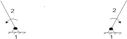
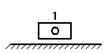
Let's conditionally call the leading link and the rack, which form a kinematic pair of class V, a class I mechanism (Fig. 5).
The formation of any planar mechanism can be represented as a sequential attachment of groups of links that satisfy the condition W = 0 to the initial mechanism.
leading link leading link
For example, the first group (Fig. 6.a) is attached to one class I mechanism (leading link and rack), the next group - either to the links of the first group, or partially to the links of the first group and the leading link or to the rack, etc.
Mechanisms formed by the attachment of several groups to a class I mechanism, like the mechanism itself, have a degree of mobility equal to one, since the groups do not change the degree of mobility of the mechanism to which they are attached.
Mechanisms can also be formed by joining groups simultaneously to several class I mechanisms (Fig. 6.b). In these cases, the degree of mobility of the mechanisms obtained will be equal to the number of class I mechanisms to which such groups are attached, i.e. the number of leading links of the resulting mechanism.
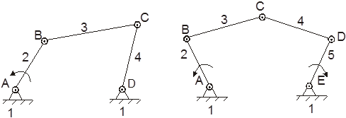
a) 2 - leading link b) 2 and 5 - leading links
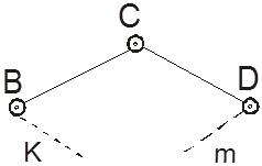
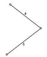
A group of links (Fig. 7), which has two links and three pairs of class V, is called a second-order class II group or a two-lead Assur group. (This group is connected to the main mechanism by two leashes BC and CD).
The order of the group is determined by the number of elements with which the group is attached to the main mechanism.
Mechanisms, which include groups of classes not higher than the second, are called class II mechanisms.
All subsequent types of group II class can be obtained by replacing individual rotational pairs with translational pairs.
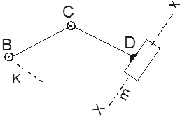
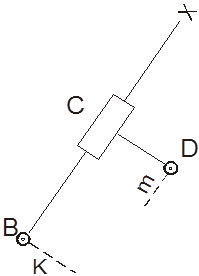
The second type is the one in which one of the extreme rotational pairs is replaced by a translational pair (Fig. 8).
The third type - the translational pair is replaced by the middle rotational pair (Fig. 9).
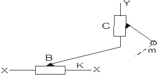
The fourth view - two extreme rotational pairs are replaced by two translational pairs (Fig. 10).

The fifth type - translational pairs are replaced by extreme and middle rotational pairs (Fig. 11).
Thus, in flat mechanisms with rotational, translational and higher pairs of classes IV and V, there are five groups of class II. Most of the modern mechanisms used in technology belong to class II mechanisms.
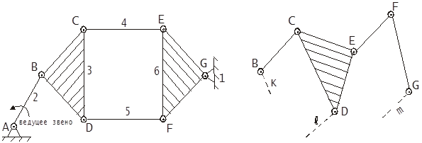
Let us now consider the second possible combination of the numbers of links and kinematic pairs. The next group in terms of the number of links should contain four links and six pairs of class V (Fig. 12). For this combination, three types of kinematic chains can be obtained, the structural principles of formation of which are different.
The first kinematic chain is a more complex open kinematic chain and is a class III group of the third order and is called a three-lead group.
The EFC link is the basic link.
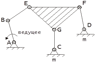
Mechanisms, which include groups not higher than third-order class III groups, are called class III mechanisms (Fig. 13).
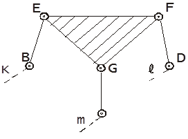
The second kinematic chain is a closed kinematic chain, which is attached to the links "k" and "m" of the main mechanism not by elements of the leashes, but by free elements B and G belonging to the basic links (Fig. 14).
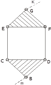
This group, in addition to two basic units BCD and EGF, which form two rigid closed loops, has one movable four-sided closed loop CEFD (Fig. 15).
Groups that include movable four-sided closed circuits are classified as groups of class IV.
The third type of kinematic chain: this chain breaks up into two simple groups of class II - BCD and EFG - and therefore belongs to those previously considered and does not represent anything fundamentally new (Fig. 16).
Rice. 1.15 Fig.1.16
Therefore, the class II group includes a one-sided circuit, the class III group - a three-sided closed circuit, the class IV group - a closed four-sided circuit. All considered groups are obtained by corresponding changes in the structure of the contours.
Generalized coordinate mechanical system(mechanism) is called an independent coordinate that uniquely determines the position of the system in space.
The number of generalized coordinates determines the number of degrees of freedom of the system.
free solid(link) in space has 6 degrees of freedom, i.e. it can make 3 independent translational movements along mutually perpendicular axes and 3 rotational movements around the same axes.
If the link is included in the kinematic pair, then its relative movement, i.e. certain restrictions are imposed on the movement in relation to the second link included in this pair. These restrictions are called link conditions - S.
According to the number of connection conditions imposed on the relative movements of the links, the pairs are divided into classes.
The class of a kinematic pair corresponds to the number of connection conditions imposed on the relative motion of the links included in this pair.
Depending on the method of connecting the links into a kinematic pair, the number of connection conditions can vary from 1 to 5.
Therefore, all kinematic pairs can be divided into 5 classes.
Class I includes pairs that impose one condition on the relative movement of links (5 moving pairs).
Class II includes pairs that impose two conditions (4-movable), etc.
If no connection conditions are imposed on the movement of a link in space, then it has 6 degrees of freedom.
Then, if the number of links in the kinetic chain is K, then total number degrees of freedom that K links have before they are connected into a kinetic chain - 6 K
(degree of freedom) before connecting to the kinematic chain.
The connection of links in a kinematic chain imposes a different number of bonds on the relative movement of the links, depending on the class of pairs.
then from the 6k degrees of freedom that the links had before their entry into the kinematic pairs, it is necessary to exclude those degrees of freedom that are taken away by the entry of the links into the kinematic pairs.
Then the number of degrees of freedom H that the kinematic chain has will be equal to:
The number W of the degrees of freedom of the kinematic chain relative to the rack is called the number of degrees of immobility (degree of immobility) of the kinematic chain.
Substituting (1) into (2):
if we denote () through n, we get:
where n is the number of moving links of the kinematic chain.
This equality is called the mobility formula or the Somov-Malyshev formula.
|
|
| a) kinematic chain |

The degree of mobility of the mechanism W is the number of independent movements that need to be brought to the mechanism in order to get one output or vice versa.
For flat mechanisms, the formula is applied Chebyshev:
W \u003d 3n - 2p 1 - p 2,(2.1)
where n- the number of moving parts of the mechanism;
p1- number of single-moving kinematic pairs;
p2- number of two-moving kinematic pairs.
In spatial mechanisms, the degree of mobility is determined by the formula Somova-Malysheva:
W \u003d 6n - 5p 1 - 4p 2 - 3p 3 - 2p 4 - p 5,(2.2)
where p 3- number of three-moving kinematic pairs;
p 4- number of four-moving kinematic pairs;
p 5- the number of five-moving kinematic pairs.
Most mechanisms have a degree of mobility W=1. They are called rational. These mechanisms are not sensitive to mounting, manufacturing and deformation errors. Such mechanisms do not require running-in.
For differential gears W=2, for robots and manipulators W=4-8, at the main mechanism of the excavator W=4. If a W=0, then we get a fixed structure - a farm.
Structural principle of formation of mechanisms. Assur groups
The basic principle of the formation of mechanisms was first formulated in 1916 by the Russian scientist Leonid Vladimirovich Assur, a professor at the St. Petersburg Polytechnic Institute.
According to the idea of L.V. Assura, any mechanism is formed by serial connection to the leading links and the rack of kinematic chains that satisfy the condition that the degree of their mobility W=0.
The leading link included in a single-moving kinematic pair with a rack forms the initial mechanism.(Fig. 2.1 a, b).
The leading link can be either a crank or a slider. The initial mechanism is assigned 1 class. The degree of mobility of the initial mechanism W =1.
 Kinematic chains, in which the degree of mobility W=0, are called Assur groups.
|
|||||
|
|||||
|
|||||
Initial Assura Group Assura Group Mechanism
mechanism II class II class
Using the above definitions, we can say that any mechanism is formed by adding Assur groups to the initial mechanism.
Types of Assur groups II class
Consider kinematic chains, which include only single-moving kinematic pairs.
For the Assura group
![]() or (2.3)
or (2.3)
Since the number of kinematic pairs must be integers, the number of links in the Assur group can only be an even number. Therefore, equality (2.1) can be satisfied by the following series of numbers:
n(number of moving parts) 2 4 6
p1(number of single-moving pairs) 3 6 9
Assur group class II III IV, etc.
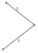
The class II Asura group may include: 2 moving links and 3 kinematic pairs , which are needed to attach the links to the rack or to other links. If we denote the rotational kinematic pair AT, and progressive P, then the following types of Assur groups of class II are possible:
1.VVV(fig.2.2); 2. GDP(fig.2.3); 3. ERW(fig.2.4); 4. PPV (Fig. 2.5); 5. PVP (Fig. 2.6).

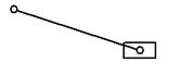
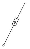
Fig.2.2 Fig.2.3 Fig.2.4
 |

Fig.2.5 Fig.2.6.
It would seem that, following the path of replacing rotational pairs with translational ones, it would be possible to replace all three rotational pairs with translational ones ( RFP). But in this case, when attached to the rack, this Assur group will turn into a flat mechanism with only translational pairs - a wedge mechanism (Fig. 1.7).
Assur groups distinguish between internal and external kinematic pairs.
Determination of the degree of mobility of the mechanism
Determination of the degree of mobility of a spatial kinematic chain
Let we have n links from which the kinematic chain is assembled. While the links are not connected in kinematic pairs, each of them has six degrees of freedom (degrees of freedom). All links before joining into a kinematic chain therefore had 6n degrees of freedom. After assembling the links into a kinematic chain, we will obtain kinematic pairs of different classes (with different degrees of mobility). Let us assume that our kinematic chain has kinematic pairs of all five classes. We accept the following notation:
P 5 - the number of kinematic pairs of the fifth class in the kinematic chain formed by us,
P 4 - the number of kinematic pairs of the fourth class,
P 3 - the number of kinematic pairs of the third class,
P 2 - the number of kinematic pairs of the second class,
P 1 - the number of kinematic pairs of the first class.
Each kinematic pair restricts the movement of links, takes away from them as many degrees of freedom as its class. Each kinematic pair of the 5th class selects 5 degrees of freedom from the links. All pairs of the fifth class will be taken away from the links 5P 5 degrees of freedom, the fourth class - 4P 4, the third - 3P 3, the second - 2P 2, the first - 1P 1. If all the lost degrees of freedom are subtracted from the total number of degrees of freedom of the links 6n, we obtain the number of degrees of freedom of the kinematic chain W:
W \u003d 6n-5P 5 -4P 4 -3P 3 -2P 2 -1P 1. (one)
The degree of mobility of the mechanism it is customary to name the number of independent coordinates that are extremely important to set to determine the positions of the links of the mechanism in the coordinate system rigidly connected to the rack.
The mechanism differs from the kinematic chain in that it has one link completely fixed. The fixed link lost all six degrees of freedom. Therefore, the number of moving links in the mechanism is n-1. Substituting the number of moving links n-1 into formula (1), we obtain a formula for determining the degree of mobility of the mechanism:
W=6(n-1)-5P 5 -4P 4 -3P 3 -2P 2 -1P 1 . (2)
Formula (2) was first obtained by Malyshev for spatial mechanisms.
Consider the Malyshev formula for determining the degree of mobility of flat mechanisms. All links of a flat mechanism can have three degrees of freedom, and kinematic pairs, respectively, can have 1 or 2 degrees of freedom. If planar kinematic pairs are considered by classes, then they are only of the fifth and fourth classes. At the same time, it is extremely important to take into account that the total number of degrees of freedom of all links of the flat mechanism is 3(n-1). Pairs of the fifth class lose two degrees of mobility, the fourth - one. Thus, the degree of mobility of the flat mechanism must be determined by the formula:
W=3(n-1)-2P 5 -P 4 . (3)
Formula (3) for determining the degree of mobility of a flat mechanism was first obtained by P. L. Chebyshev.
Taking into account the dependence of the number of general conditions of relations imposed on the mechanism, the mechanisms are divided into families.
The families of mechanisms and their structural formulas are shown in Table 1.
Table 2.1 Structural formulas of various families of mechanisms

Consider Application structural formula Chebyshev P. L. on a specific example. Figure 5 shows an articulated four-link.
1e- link- crank- commits rotary motion around the O axis ( full turn);
2e- link AB - connecting rod - makes a plane-parallel movement;
3e- link BC - rocker (or balancer) - performs a reciprocating rotational movement around the C axis ( incomplete turnover);
4e- OS link - stand (bed) - fixed link.
Number of links n=4. Kinematic pairs: 4-1, 1-2, 2-3, 3-4. We have 4 single-moving pairs 5 th class. The relative motion of all links is flat. The mechanism is flat. We determine the degree of its mobility according to the formula of Chebyshev P. L.:
W=3(n-1)-2P 5 -P 4 =3(4-1)-2×4-0=1.
The mechanism has a degree of mobility equal to 1. This means that it is enough to set one coordinate to any link of the mechanism in the coordinate system rigidly connected to the frame in order to determine the positions of all other links. For example, in our case, it is enough to set the angle of rotation of the crank j 1 .
 Passive Links and Redundant Links
Links and kinematic pairs, which do not affect the nature of the movement of the mechanism as a whole, are called redundant (extra) links and pairs, and the bonds conditioned by them are called passive bonds.
When determining the degree of mobility of the mechanism, redundant links and kinematic pairs should not be taken into account.
In complex rod mechanisms, it is not always possible to determine the degree of mobility by eye. In these cases, it is extremely important to use the Chebyshev formula.
 Let's define W of the double parallelogram mechanism (Figure 6). Here AB=BC=KM=MN; AN || BM || CK; AN=BM=CK and AC || K.N. With such a ratio of links, the mechanism has W=1, i.e., it is enough to set the position of link 1 by the angle j 1 to determine the positions of all other links. If you fix link 1 in any position, then the remaining links will be motionless. We define W by the Chebyshev formula. Number of links - n=5, kinematic pairs 5 th class Р 5 =6, the number of kinematic pairs of the fourth class - Р 4 =0.
W=3(n-1)-2P 5 -P 4 =3(5-1)-2×6-0=0.
If W=0, then there should be not a mechanism, but a rigid farm. We see that the mechanism can carry out movement. In case if in this mechanism mentally remove link 5 (or 2), then the nature of the movement of the remaining links will remain unchanged. The mechanism turns into an ordinary four-link, W of which we have already determined - W=1. When link 5 is eliminated, 2 kinematic pairs are simultaneously eliminated: 5-1, 5-3. Consequently, in this mechanism, one link and two kinematic pairs are redundant.
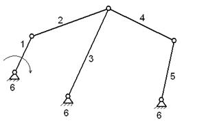
 Consider another example - the Marcus mechanism, often used as a drive for a swinging conveyor (Figure 7). Number of links n=6. Kinematic pairs: 6-1, 1-2, 2-3, 2-4, 3-4, 3-6, 4-5, 5-6 all fifth class R 5 = 8, R 4 = 0 .
We define W by the Chebyshev formula:
W=3(n-1)-2P 5 -P 4 =3(6-1)-2×8-0=-1.
According to the scheme of the mechanism, it can be seen that it will work and W=1.
Let there be no direct connection of links 2-3. Links 3, 4, 5 will still take a position corresponding to the angle of rotation j 1 of link 1, since links 1, 2, 4 must be fixed at this angle. The same can be obtained if the kinematic pair 2-4 or 4-3 is removed. Here one kinematic pair is redundant. It can be ignored. Then:
W=3(6-1)-2×7=1.
At the same time, we note that the elimination of the link entails the elimination of some kinematic pairs.
Hosted on ref.rf
The elimination of kinematic pairs (the cessation of the contact of the links) does not entail the inevitable elimination of the links included in it.
The connection of links, where 3 or more links are connected, is commonly called node. There is one kinematic pair in a node less than links.
 Excessive kinematic pairs and links impose additional conditions on the accuracy of the manufacture of the mechanism, however, despite this, a passive link or an extra connection is sometimes introduced into the mechanism in order to obtain any additional necessary qualities; increase in strength, decrease in friction, etc.
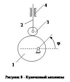
Let's determine W of the cam mechanism shown in Figure 2.8. Here the links are 1 - cam, 2 - pusher, 3 - roller, 4 - rack. Number of links n=4. Kinematic pairs 1-4, 2-4, 2-3 of the fifth class and 3-1 - the highest flat kinematic pair 4 th class.
When the cam is rotated through an angle j, the pusher will take a certain position. At first glance W=1. We define W by the Chebyshev formula:
W=3(4-1)-2×3-2=2.
There is an extra degree of mobility here. If the roller was fixed with a pusher, then W of the mechanism would be equal to one. Rotation of the roller in relation to the rest of the links has no effect. The angle of rotation of the roller is the extra degree of freedom of the mechanism.
An extra degree of freedom it is customary to call such a degree of freedom in the movement of some links, the elimination of which does not cause changes in the nature of the movement of other links for kinematic considerations.
This refers to the absolute or relative movement of the link. The elimination of an extra degree of freedom does not entail the elimination of the link.
Before using the Chebyshev formula, it is extremely important to mentally exclude passive constraints and extra degrees of freedom from consideration.
The Chebyshev formula generally gives the correct answer. In general cases, passive connections and extra degrees of freedom do not exist and exist only in special cases.
For example: the double parallelogram mechanism is a special case of the same mechanism when the links are not parallel (Figure 9a); the Marcus mechanism is a special case of the mechanism, when the axes of the swivel joints of links 2, 4 do not coincide (Figure 9b); a round roller is a more particular case of the geometric shape of a roller round shape(Figure 9c).
Thus, the Chebyshev formula makes it possible to identify characteristics(in particular) mechanisms.
Determination of the degree of mobility of the mechanism - the concept and types. Classification and features of the category "Determination of the degree of mobility of the mechanism" 2014, 2015.


 Английский вокруг нас исследовательская работа")
