Graph of current versus resistance. Dependence of current strength on resistance
If you want to figure out how current depends on voltage, you first need to remember from the school curriculum what current is and what voltage is. Electric current - movement along a certain trajectory of charged particles, they are also called electrons. In a school textbook on physics, this quantity had the following designation - I and was called current strength. Voltage has the designation U, and this, in general, is the potential difference that are located at the ends of the electrical circuit. Due to this condition, the electrons move like the movement of a liquid.
1 ) Current and voltage measurement
Directly proportional the relationship between these two described quantities has been described for a long time, and is called Ohm's law. Ampere is used to measure current. To determine the current strength in electrical circuits, a special device is usually used, it is called ammeter.
In order to measure voltage, they usually use a special device - voltmeter, and the unit of measurement is volt.
For clarity, if you have the opportunity, you can assemble an electrical circuit. Its components will be: resistor, directly current source, you will also need an ammeter and a device such as a voltmeter.
First of all, try to close the circuit when current flows through it, look at the readings that both devices show. After that, change the voltage at the ends of the resistance. In the second case, in comparison with the first, you will note that the readings on the ammeter screen will increase with increasing voltage, respectively, and vice versa. Conducting this experiment will help to visually see this described in Ohm's law directly proportional relationship between current and voltage.
2) The movement of electric current
Electric current can be described as something similar to the flow of a liquid, this comparison is given for clarity. In this flow, all charged particles move not in the cavity of the pipe, but along a certain conductor. Depending on the material of the conductor, the nature of the movement of particles can be different. In order to perform a quantitative description of this phenomenon, the R value was applied. R - this value is called electrical circuit resistance, this value is measured in ohms.
The magnitude of the current strength will increase depending on the increase in voltage and the decrease in the resistance of the circuit section, it is this dependence that is described in Ohm's law: I \u003d U / R.
In the building of the Kunstkamera there is a museum of M.V. Lomonosov. Presentation for the 300th anniversary of M.V. Lomonosov. I am not thirsty for transparent streams, But the pleasant noise in the green groves Hastily and joyfully attracts me. Lomonosov Bridge. Books by M.V. Lomonosov from the funds of the Main Library. Glass-blowing workshop... Lomonosov is a scientist, naturalist, poet, artist, historian, chemist, physicist, astronomer, metallurgist. 1753 Ust Ruditsa - the first factory for the production of glass beads, beads and smalt for the revival of mosaic art.
"Electrolysis of solutions and melts" - Schemes of processes. Electrolytes - complex substances, whose melts and solutions conduct electricity. Movement of electrons in a metal crystal. The oxidation states of Cu and Fe have changed. Anode. Safety regulations. Michael Faraday (1791 - 1867). The process of donating electrons by ions is called oxidation. Safety rules for working on a PC. The movement of ions in the electrolyte under the action of electric field. Change z.I.
"Heat engine" - Various types of steam locomotives. The first steam locomotive was designed in 1803 by the English inventor Richard Trevithick. Scottish engineer, mechanic and inventor, interested in steam and water condensation. After 5 years, Trevithick built a new steam locomotive. James Watt (1736-1819). The development of energy is one of the most important prerequisites for scientific and technological progress. Watt machine. The history of the development of thermal engines.
"Internal energy of physics" - At the challenge stage, students make their assumptions, i.e. put forward a hypothesis. How many ways are there? Experiment. U. Presentation support of the lesson. What do you expect or need to know? U=Ek+En. Logbook. Discuss what you have read as a group. 2. Experience 3.
"Mechanical waves grade 9" - Riddles. B. The process of propagation of oscillations in any medium or vacuum. Front shape. The source oscillates along the OX axis. ? - frequency, xm - amplitude, v - speed, ? - length. And there are no waves and the wind has died down ... D. Any process that takes place in an elastic medium. Nature. Energy. Model of an elastic medium. Wavelength, ?: ? =v? T or? = v: ? [?] = m. Plane wave. Words are not enough to describe everything, The whole city is skewed.
"Flat Mirror" - Step back from the mirror two steps. Experience shows that the image is obtained: Kaleidoscope. Circus focus. Flat mirrors are used in some circus tricks. The use of mirrors in technology. Construction of an image in a flat mirror. The use of a flat mirror. Mirror plates are installed inside the tube at an angle of 600. The trick “a living head without a body” is known. From each point of the candle, rays of light diverge in all directions.
We plot the dependence of the current in the first branch on the resistance of this branch according to equation (6.2), which, for the chosen values of , and takes the form:
![]() .
.
Substituting here various values of resistance , we arrive at the results shown in Fig. 8.3.
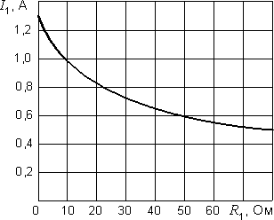
Rice. 8.3. Current versus resistance
8.3. External characteristic of the energy source
The external characteristic of the energy source (generator) is the dependence of the voltage at its terminals on the current flowing through it. For the circuit shown in Fig. 8.4, a,
it is expressed by the equation ![]() . In accordance with this equation, the voltage at the terminals of the source is less than the EMF by the amount of voltage drop across its internal resistance. The general view of the characteristic is shown in fig. 8.4, b.
. In accordance with this equation, the voltage at the terminals of the source is less than the EMF by the amount of voltage drop across its internal resistance. The general view of the characteristic is shown in fig. 8.4, b.
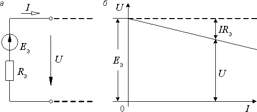
Rice. 8.4. External characteristic energy source
8.4. Potential Diagram
A potential diagram is a graph of the potential distribution along a certain contour. According to the assignment, this circuit should include two sources of EMF. This may be, for example, a circuit consisting of the first, fourth and third branches (see Fig. 2.1). On fig. 8.5 it is shown separately.
point between EMF source and denote resistance 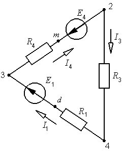
some letter, for example, a letter d. The potentials of points 2, 3 and 4 are known from the method of nodal potentials, and for points m and d we make the following calculations:
Or ![]() .
.
Suppose we are given the following resistance values:
30 ohm; = 26 Ohm; = 59 Ohm,
and for the potentials we get:
0; = -15 V; = 70 V; = 48 V; = 28 V.
The potential diagram corresponding to these data is presented in fig. 8.6.
When constructing a diagram, we go around the contour clockwise, starting from point 4 (in general, we choose the starting point and the direction of bypassing the contour arbitrarily). On the abscissa axis, we plot the values of the resistances in the sequence in which they occur to us, and along the ordinate axis, the potentials of the corresponding points.
The potential diagram gives full information about the circuit in question. In addition to resistances, it shows the magnitude and direction of the EMF. It can also be used to determine the voltage between any two points. On fig. 8.6 shows how the voltage between points 3 and 2 is determined. It is equal to
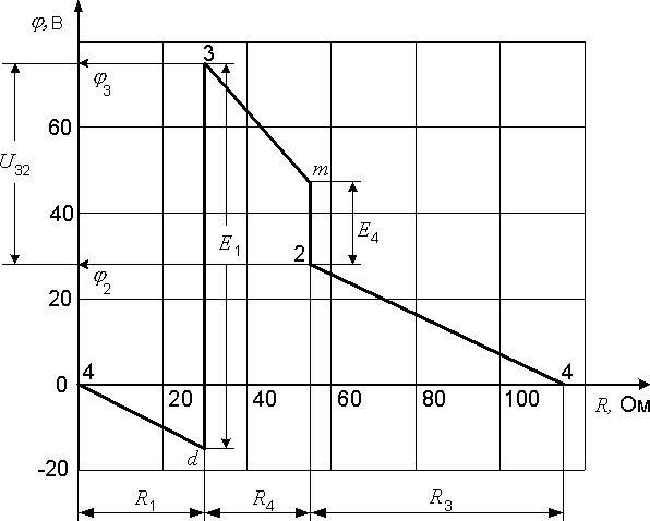
Rice. 8.6. Potential Diagram
9. The content of the calculation and graphic tasks on the topic "calculation of the electrical circuit of a single-phase sinusoidal current"
9.1. Task number 1
For the scheme assigned to the student in accordance with his option (see subsections 9.4 and 9.5), the following is required:
1) write equations according to Kirchhoff's laws and the method of loop currents (you should not solve these equations);
9.2. Task number 2
1. Write expressions for the instantaneous values of the found currents. Draw a wave diagram of the current.
2. Construct a vector topographic voltage diagram, combining it with a vector current diagram
3. Determine the reading of the wattmeter and the voltage between the points m and n.
9.3. Task number 3
1. Convert the given electrical circuit, presenting it as a series connection of an equivalent generator and a variable element of the third branch (crossed out in the diagram with an inclined arrow).
2. For the resulting unbranched circuit, construct a circular current diagram.
3. Find the value of the current from the circular diagram for a given value of the value of the variable resistance.
4. Construct a graph of the dependence of the current of the third branch on the value of the variable resistance:
a) using a pie chart;
b) calculation according to the formula of Ohm's law.
Variants of schemes and data for calculation are given below.
The dependence of the current on the voltage. Electrical resistance of conductors. units of resistance. 8th grade
1. Educational.
- consolidate knowledge on previous topics,
- show the dependence of current on voltage,
- define the concept of resistance
- teach practical application of knowledge gained in physics lessons.
- expand interdisciplinary connections.
- generate interest in the subject, study,
- nurture initiative, creative attitude.
- to develop the physical thinking of students, their creative abilities, the ability to independently formulate conclusions,
- expand your curiosity.
- develop speech skills.
Equipment for the lesson: Demo ammeter - 1 pc, demo voltmeter - 1 pc, demo key - 1 pc, resistance box - 1 pc, tripod, overhead projector. connecting wires - 6 pcs per desk, ammeter - per desk, voltmeter - per desk, key, resistor - per desk, current source (battery) - 3 pcs, rectifier - per desk, code positives.
1. Organizational moment
2. Repetition of previous topics
3. Explanation of new material
4. Practical work
5. Problem solving. Anchoring
6. Summing up the lesson
7. Homework
Teacher. Hello kids, sit down. Write down the day and month in your notebooks.
Before writing down the topic of our lesson, let's remember what you have learned in previous lessons, as your knowledge will be needed to study our topic.
There are two appliances on your tables. Who among you can name these devices? What are they for? What is the difference?
Student. Ammeter for measuring current, letter A. Voltmeter for measuring voltage, letter V.
Teacher. There is even a poem about the ammeter:
I am a well-known device
I turn on interesting.
I'm welcome in any chain.
I am not a barrier to charges.
I will serve you:
I'll show you the power.
What is the difference between connecting an ammeter and a voltmeter to a circuit?
Student. The ammeter is connected in series, the voltmeter in parallel.
To connect everything correctly,
Gotta repeat quickly.
Everyone knows for sure, therefore.
The ammeter is connected in series
A voltmeter is in parallel.
Determine the division value of the ammeter and voltmeter.
Student. We take the next two numbers and find their difference. We divide this difference by the number of divisions between these numbers.
Each student has a sheet with a surname on the table, on the sheet they write down the value of the division of the ammeter and voltmeter.
Teacher. And now, attention to the screen (the overhead projector turns on). On the diagram screen.
Look for errors in the diagrams.
Student. In diagram 1, the direction of the electric current is indicated incorrectly, the voltmeter is connected in series, it is necessary in parallel to the lamps. In circuit 2, swap the voltmeter with the ammeter. In circuit 3 there is no current source.
Teacher. And now, the question (highlighted on the overhead projector). Write next to each physical quantity: on the left is the letter designation, and on the right is the unit of its measurement.
Current strength -
- voltage -
- charge -
The students continue to write down their answers on the sheets of paper.
Teacher. We know that electric current is the ordered movement of charged particles in an electric field. And the stronger the action of the electric field on these particles, the greater the current strength. But the action of an electric field is characterized by a physical quantity - voltage. Therefore, it can be assumed that the current strength depends on the voltage. Write down the topic of the lesson (you can ask questions about I and U).
And now consider this experience: in front of you is an electrical circuit of an ammeter, voltmeter, key, spiral, connecting wires, battery. Determine the division value of the voltmeter and ammeter. We close the circuit and note the readings of the instruments.
The students themselves read the readings of the ammeter and voltmeter.
Teacher. What do you think will happen if we connect another battery? (connection).
Student. The voltage increased and the current increased by the same amount.
Teacher. (All readings are written on the blackboard.) And if we connect another battery.
Student. Voltage and current increased by the same number of times.
Teacher. What conclusion can be drawn?
Student. How many times the voltage applied to the same conductor increases, the current strength in it increases so many times.
Teacher. In other words, the current in a conductor is directly proportional to the voltage at the ends of the conductor. Write it down. And draw the electrical circuit of this experiment.
Teacher. And now let's consider the experiment: let's close the key. What are the readings of the ammeter and voltmeter. And now in the resistance store we will change the conductor. And we'll connect. What do we see?
Student. The current has changed. voltage - no
Teacher. We continue to change conductors. What do we see?
Student. With different conductors, the ammeter readings are different, the current strength is different. And the voltmeter shows the same voltage.
Teacher. This means that the current strength in the circuit depends not only on the voltage, but also on the conductor included in the circuit. The dependence of the current strength on the properties of the conductor is explained by the fact that different conductors have different electrical resistance. Resistance is a characteristic of a conductor. Resistance is denoted by the letter R.
1 Ohm is taken as a unit of resistance - the resistance of such a conductor, in which, at a voltage at the ends of 1V, the current strength is 1A.
This physical quantity, a unit of measurement named after the German physicist Georg Simon Ohm, who first introduced the concept of resistance into physics and established the basic law of electrical circuits, which you will meet later.
Other units of resistance are also used
1mΩ = 0.001Ω 1kΩ = 1000Ω, 1MΩ = 1000000Ω
What is the reason for the resistance? You know that at the nodes of the crystal lattice of a metal there are positive ions, and free electrons move in the space between them. But they cannot move indefinitely, as they interact with the ions of the metal crystal lattice, repel each other with ions. That is, ions interfere with the movement of electrons in metals, as if they resist.
So, the reason for the resistance is the interaction of moving electrons with the ions of the crystal lattice.
For comparison, a resistance of 1 ohm has 5 km of a tram contact wire or 114 m of wiring in an electrical network.
The iron has a spiral - 50 ohms, a flashlight bulb - 12 ohms.
Fizkultminutka. (Students get up).
Teacher. Imagine that you are charged particles that, while there is no electric current, oscillate around their places (students oscillate). There is an electric current and the charged particles will move in the direction of action on them electrical forces. Let the board be negatively charged, the opposite wall be positively charged (students begin to move from wall to board slowly with outstretched arms). The direction of the current changes from the board to the wall (children turn and move towards their place).
Teacher. Now let's make a small practical work. Assemble an electrical circuit consisting of appliances located on the tables. Record the readings of the ammeter and voltmeter. But first, let's remember the safety precautions:
If, say, you noticed
What is some device
Unharmed and whole and even
Might show something
Feel free to hit him against the wall
And kick him with your feet
And drop it (by chance)
Right on the floor from the table.
And when the instrumentation is in the classroom
won't stay at all
Imagine how happy they will be
All students at once
Because your teacher
Can't live without appliances
And then you have to go to school
Of course, the opposite is true, the devices must be handled with care.
The students assemble the chain and show it to the teacher. Record the readings of the ammeter and voltmeter.
Now we will collect the chain,
We take the rectifier,
Wires and ammeter,
Key resistor and voltmeter.
Place the devices in the circle.
The voltmeter is connected in parallel.
Now check the whole circuit
Measure current, voltage
Remove the indication.
Do not forget to specify the units of measurement.
Draw a diagram too
Then disassemble the chains
Fold everything carefully.
Teacher. Let's solve the problem. Ex. 19(1)
Teacher. Now imagine for a moment what would have happened if mankind had not discovered electricity. We would be left without lighting, household appliances, TVs, computers, and would not be able to listen to music. Fortunately, thanks to the work of the great scientists of the 19th century, an electrical revolution took place in the world, and we are now using its fruits: electric current, voltage.
To distant villages, cities
What's on the wire?
bright majesty -
It is (all together) electricity.
We deserve a moment of rest. Thank you for your attention and lesson.
To sum up the lesson: So, the current strength in the conductor is directly proportional to the voltage at the ends of the conductor. The strength of the current depends not only on the voltage and on electrical resistance. Different conductors have different resistance. Measured in ohms.
More information
In the building of the Kunstkamera there is a museum of M.V. Lomonosov. Presentation for the 300th anniversary of M.V. Lomonosov. I am not thirsty for transparent streams, But the pleasant noise in the green groves Hastily and joyfully attracts me. Lomonosov Bridge. Books by M.V. Lomonosov from the funds of the Main Library. Glass-blowing workshop... Lomonosov is a scientist, naturalist, poet, artist, historian, chemist, physicist, astronomer, metallurgist. 1753 Ust Ruditsa - the first factory for the production of glass beads, beads and smalt for the revival of mosaic art.
"Electrolysis of solutions and melts" - Schemes of processes. Electrolytes are complex substances whose melts and solutions conduct electricity. Movement of electrons in a metal crystal. The oxidation states of Cu and Fe have changed. Anode. Safety regulations. Michael Faraday (1791 - 1867). The process of donating electrons by ions is called oxidation. Safety rules for working on a PC. Movement of ions in an electrolyte under the action of an electric field. Change z.I.
"Heat engine" - Various types of steam locomotives. The first steam locomotive was designed in 1803 by the English inventor Richard Trevithick. Scottish engineer, mechanic and inventor, interested in steam and water condensation. After 5 years, Trevithick built a new steam locomotive. James Watt (1736-1819). The development of energy is one of the most important prerequisites for scientific and technological progress. Watt machine. The history of the development of thermal engines.
"Internal energy of physics" - At the challenge stage, students make their assumptions, i.e. put forward a hypothesis. How many ways are there? Experiment. U. Presentation support of the lesson. What do you expect or need to know? U=Ek+En. Logbook. Discuss what you have read as a group. 2. Experience 3.
"Mechanical waves grade 9" - Riddles. B. The process of propagation of oscillations in any medium or vacuum. Front shape. The source oscillates along the OX axis. ? - frequency, xm - amplitude, v - speed, ? - length. And there are no waves and the wind has died down ... D. Any process that takes place in an elastic medium. Nature. Energy. Model of an elastic medium. Wavelength, ?: ? =v? T or? = v: ? [?] = m. Plane wave. Words are not enough to describe everything, The whole city is skewed.
"Flat Mirror" - Step back from the mirror two steps. Experience shows that the image is obtained: Kaleidoscope. Circus focus. Flat mirrors are used in some circus tricks. The use of mirrors in technology. Construction of an image in a flat mirror. The use of a flat mirror. Mirror plates are installed inside the tube at an angle of 600. The trick “a living head without a body” is known. From each point of the candle, rays of light diverge in all directions.


