Virtual reality. Singing with a computer program. Female Voice Synthesizers
As already shown in Chap. 2, in the process of electromechanical conversion of signals in electrodynamic GGs, different kinds non-linear distortions, which can be evaluated in both frequency and time domains. physical processes, causing these non-linear distortions, can be classified as follows: non-linear elastic oscillations of the elements of the moving system - suspensions, washers, diffusers, caps; oscillatory processes in the presence of mechanical defects in the GG, perceived as rattling or overtones; parametric oscillations of diffusers; frequency modulation of the emitted signal due to Doppler effects, non-linear electromechanical transformations in the "voice coil + magnetic circuit" assembly. Let us consider these processes and methods for their calculation in more detail.
Nonlinear elastic oscillations of the elements of the GG mobile system - suspensions, washers, diffusers. Experimental studies of harmonic distortions in serial loudspeakers show that they reach the highest values in the low-frequency part of the reproduced GG range, where the displacement amplitudes of the moving system are especially large (Fig. 3.32). Nonlinear distortions in the low-frequency region, where the cone oscillations are of a piston nature, are mainly determined by the nonlinearities of the characteristics of the suspensions (corrugated suspension and centering washer) and the electromagnetic conversion in the "voice coil + magnetic circuit" assembly.
Rice. 3.32. The dependence of K G on the frequency and magnitude of the input voltage, 1 - U \u003d 4 V; 2 - U = 2 V; 3 - U = 0.63 V
Influence magnetic field for non-linear distortion will be discussed in § 3.8. As follows from the general theory, the nature of a nonlinear oscillatory process in an elastic system is determined, respectively, by its nonlinear elasticity, nonlinear inertia, and nonlinear damping. The behavior of the system in the resonance region depends on the ratio of these factors. The resonant frequency, which in nonlinear systems depends on the amplitude, in the case of the predominance of nonlinear elasticity will increase with increasing amplitude. With the predominance of nonlinear inertia, the ratio will be inverse. The resonant amplitude curve ("pulling phenomenon") will be tilted by the peak towards higher frequencies with the predominance of nonlinear elasticity and towards lower ones with inertia, etc. Experiments to study the nature of resonance amplitude curves in the low-frequency region made it possible to establish that the main determining factor in GG is a non-linear elasticity.
Sufficient attention was paid to the study of non-linear distortions in the GG in the low-frequency region in the technical literature, however, in all works, the moving GG system was replaced by a system with lumped parameters, but since the dependencies between these parameters and the design and physical and mechanical parameters of the suspensions were not established, the analysis did not allow practical calculations.
Executed for last years a large amount of experimental and theoretical research made it possible to develop a method and create a package of applied programs for computers for calculating the nonlinear distortions of the HG in the low-frequency region, due to the elastic characteristics of the suspensions. To calculate the elastic characteristics of the moving system in the low-frequency region, the calculation model shown in Fig. 1 was adopted. 3.33. The diffuser is considered as a system consisting of three shells: a non-sloping corrugated sinusoidal shell 1 (this type of suspension is often used for mass types of GG); a gently sloping rectilinear conical shell 2 (in the low-frequency region, where the wavelength is large compared to the dimensions of the GG, such a model is justified for any diffuser shape); flat section 3 (representing a dust cap) and an elastic base 4 (the parameters of which are determined from experimental measurements elastic characteristics of centering washers). The profile of a sinusoidal non-hollow corrugated suspension is quite accurately described by the equation (see Fig. 3.19):
where τ = ω 1 ρ - τ 0 ; ω 1 \u003d 2πRδ 1 /l - π; ρ = r/R; δ 1 \u003d r 1 /R.
The deformed state of the shell can be described by two functions: υ(ρ) is the angle of rotation of the tangent to the surface; ψ(ρ) - stress function (ψ) \u003d (-1 / EhR)∫T 2 dr, where T 2 is the internal normal force). To find these functions, a system of second-order differential equations is used:
for shallow corrugated casing (1):
where h - thickness, μ - Poisson's ratio; θ = ctg α 0 = F θ sinτ; F θ = ω 1 H/R; N \u003d -ω 1 F 2 θ sin2τ / 2 (1 + θ 2); K \u003d 12 (1 - μ 2) R 2 / h 2;
for a shallow conical shell (2):
ρψ .. K + ψ . K - 1/ρψ K = (cosβ/sin 2 β)⋅υ K ,
ρυ .. to + υ . to + 1/ρυ to = -K to (cosβ/sin 2 β)ψ to + (K to /sin 2 β)F to; (3.28)
for a round flat plate (cap) (3):
ρψ .. n + ψ . n - 1/ρψ n = 0,
ρυ .. n + υ . p - 1/ρυ p = K p Ф p, (3.29)
where F, F k, F p is a function of the forces of inertia q applied to the diffuser force Q c and the elastic force of the reaction created by the washer Q w. By setting the law of change of the angle of rotation υ in the form υ = - f⋅3ρ(1 - ρ) 2 , taking into account the boundary conditions of the conjugation of the shells (the equality of normal forces and radial displacements at the conjugation points), the integration of equations (3.27), (3.28), ( 3.29) by the Bubnov-Galerkin method, which makes it possible to construct the elastic characteristic of the moving system:
Q c = B 1 w + B 2 w 2 + B 3 w 3 , (3.30)
where B i = C i + S i (i = 1, 2, 3), C i - coefficients determined by the design and physical and mechanical parameters of the corrugated suspension, diffuser and cap; S i - coefficients of elastic characteristics of the centering washers, which are determined from experimental data, w - displacement of the center of the system. The obtained measurement data for deflections of centering washers commercially produced by GG and their statistical processing made it possible to develop a computer program for polynomial approximation of the measurement results by the least squares method using orthogonal Chebyshev polynomials. The results of measurements and approximation of elastic characteristics, taking into account the spread of centering washers for loudspeakers with a diameter of 160, are shown in fig. 3.34. The values of the coefficients of the approximating polynomials and the boundaries of the intervals in this case have the form:
Q w 1 \u003d 1.03 ⋅ 10 2 w + 3.06 ⋅ 10 3 w 2 + 1.24 ⋅ 10 7 w 3,
Q w 2 \u003d 3.42 ⋅ 10 2 w - 3.21 ⋅ 10 4 w 2 + 3.4 ⋅ 10 7 w 3. (3.31)
An analysis of the influence of the nonlinearity of the elastic characteristics of washers on the general elastic characteristics of the moving system shows that, in general, the nonlinearity of the washer is higher than the nonlinearity of the suspension, especially at low levels of the applied voltage. In particular, calculations according to (3.30) have established that the cubic terms in the elastic characteristics of the moving system are mainly determined by the elasticity of the centering washers. The results of these calculations made it possible to determine quantitative relationship coefficients B i with the parameters of the moving system. So, with a decrease in the thickness h of the suspension, the initial stiffness B 1 decreases, and the nonlinearity B 2 , B 3 increases; as the suspension corrugation depth H increases, the initial stiffness decreases, but the cubic terms in (3.30) may not decrease, so an increase in H without changing other parameters may not lead to a decrease in nonlinear distortions.
The developed method for calculating the elastic characteristics of mobile systems made it possible to proceed to the calculation of forced nonlinear oscillations of the mobile GG system in the low-frequency region. The differential equation of forced low-frequency oscillations of a moving system has the form
where w is the displacement of the center of the system; α, γ, β are the reduced coefficients of the elastic characteristic (3.30) of the moving system; F - driving force; ![]()
- attenuation coefficient; Q T - quality factor. Using the harmonic balance method, solution (3.32) can be constructed in the form
w = A 1 cos(wt - χ 1) + A 2 cos(2wt - χ 2) + A 3 cos(3wt - χ 3)
where A 1 , A 2 , A 3 and χ 1 , χ 2 , χ 3 are, respectively, the amplitudes and phases of the first - third harmonics, which are functions of the design and physical and mechanical parameters of the moving system.
The calculation of the amplitude-frequency and phase-frequency characteristics, performed using a specially developed package of applied programs on a computer, made it possible to evaluate the effect on them of the quality factor of the HG, the elasticity of the centering washer, the parameters of the corrugated suspension, etc. The results of the calculations presented in Figs. 3.35 for a GG with a diameter of 160 mm show that the shape of the amplitude-frequency curves depends on the quality factor of the system. At high Q-factors (Q T > 3), a "jump" phenomenon can occur - a sharp change in the amplitude near the top of the amplitude curve (the presence of a "jump" at the GH resonance at large amplitudes was previously discovered experimentally). With decreasing quality factor Q T

As follows from the data in the table, a decrease in the quality factor significantly reduces the harmonic distortion factor. So, a change from Q T \u003d 3 to Q T \u003d 1 leads to a change in K G 2 from 6.5 to 4.2%, and K G 3 from 24.5 to 5.2%. The initial stiffness of the washer also has a significant effect (the transition from washers with the maximum stiffness for this type of GG to the minimum increases KG by almost 2 times). Nonlinear oscillations of a moving system in the low-frequency region lead to the appearance in the spectrum of the emitted signal, in addition to harmonic, intermodulation and difference distortions, which are generated by the same physical reasons - the nonlinearity of the elastic characteristics of suspensions and diffusers. To calculate such distortion in the low frequency region, the same methods are used as for calculating harmonic distortion; in this case, the right side of equation (3.32) takes the following form: F 1 cosw 1 t + F 2 cosw 2 t. Calculations of frequency-difference distortions show that amplitudes with frequencies f 2 ± f 1 have the greatest value. This is determined mainly by the quadratic nature of the elastic characteristics of the suspensions.
A change in the quality factor also has a significant effect on the level of frequency-difference distortion in the low-frequency region. Thus, a change in the quality factor from 4 to 1 leads to a decrease in amplitudes by 1.5 ... 2 times at frequencies of 125 and 180 Hz. Note that the presented computational model is applicable in the region where the diffuser oscillations are piston-like. In the frequency range where the natural frequency spectrum of the diffuser is located, it is necessary to consider the problem of nonlinear oscillations of thin elastic shells of rotation with negative Gaussian curvature. The development of programs for their calculation is currently an urgent task. Experience in the development of GG shows that all measures aimed at increasing the structural rigidity of diffusers (increase in curvature, the presence of stiffeners, etc.), as well as the use of materials or high rigidity (E / ρ) or with a large damping coefficient (γ) lead to reduce the level of non-linear harmonic distortions of the second - third order, due to the non-linear elastic characteristics of the diffusers.
Nonlinear oscillations that determine the rattling and overtones in the GG. As noted in Chap. 2, in dynamic GGs there is a special kind of non-linear distortion, subjectively perceived as rattling and overtones. Much attention was paid to the study of these processes in GG in . The characteristic sound of rattling and overtones is most often detected when the GG is excited in the region of its resonance frequency or in a wider low-frequency region up to 2 ... 3 kHz. An analysis of the features of the emission spectra of such GGs shows that the nonlinear distortions that occur in them can be divided into four types (see Fig. 2.10): lower-order harmonics with n from 2 to 4; harmonic with n from 4 to 10...12, which determine the appearance of overtones, and harmonic with n from 10 and above, perceived as rattling. In addition, the spectrum may also contain subharmonic components with frequencies of 1/2n or 1/3n, caused by parametric oscillations of the elements of the moving system.
The results of theoretical and experimental studies carried out in recent years have shown that the most information for the differential assessment of various types of mechanical defects in the HG that cause rattling and overtones is provided by the analysis of the temporal structure of the signal emitted by the loudspeaker in the near field. Statistical analysis oscillograms of the emitted signals of serial GGs, in which rattling or overtones were subjectively diagnosed, made it possible to reveal a clear correlation of various types of mechanical defects in the GG with the shape, amplitude, polarity, and location of the rattling pulses in relation to the main monoharmonic excitation signal. Nonlinear distortions, perceived in the form of rattling or overtones, are caused in GG by the spread of the physical and mechanical parameters of the materials used; non-compliance with technological regimes (processes of grinding, casting, pressing, assembly, etc.); violation of assembly technology; mechanical defects that occur during transportation and storage of the GG, etc. Violation of technological regimes in mass production causes such defects as friction of the coil in the gap of the magnetic circuit, touching the diffuser leads, impact of the moving system on the magnetic circuit, the presence of metal chips in the gap, non-uniformity of the diffuser structure, peeling of the washer, diffuser, coil, etc. Most of the above reasons (about 80%) can be considered as a combination of three main phenomena: elastic and inelastic impact of the moving system on a hard stop; dry friction when moving a voice coil in a magnetic circuit; fluctuations and touching findings on the diffuser.
Impact rattle occurs when the coil or diffuser hits a hard stop (for example, a magnetic system). In this case, the elastic impact may differ, when the mobile system (PS) bounces off the magnetic circuit according to a certain law, depending on the physical and mechanical properties of the colliding surfaces, the excitation frequency, etc. Usually this phenomenon occurs in the resonance region, where the mobile system is displaced with a maximum amplitude . The impact can also be inelastic. In this case, the moving system practically stops, which leads to the appearance of a cutoff by displacement. At the moment of impact, a shock pulse of sound pressure occurs, which is in phase with the main signal. In real loudspeakers, at the moment of impact, the sound pressure does not drop to zero, since even when the coil stops, the PS continues to shift due to inertia forces, transient processes occur, although they are less pronounced than shock impulses.
Time diagrams of displacement and sound pressure at elastic impact are shown in fig. 3.36. The structure of the rattling pulses (polarity, amplitude, steepness of the rise of the front, the duration and nature of the transient process) depends on the magnitude of the displacement, the vibrational velocity, the shape of the frequency response, the upper limiting frequency, the amplitude of the excitation signal, etc. The diagnostic characteristic of shock rattling is the polarity and amplitude of the pulse in the initial stage of its formation with respect to the excitation signal.
In case of elastic and inelastic impacts, which occur when the moving system is displaced, rattling pulses periodically appear at the tops of the positive (negative) half-waves of the harmonic signal. The polarity of the pulses coincides with the polarity of the half-waves of the harmonic signal.
Rattle due to friction usually occurs when metal chips enter the gap of the GG magnetic system and when the coil is skewed in the gap. In both cases, rubbing (due to dry friction) of the coil occurs, which leads to rattling. The rubbing of the coil can be continuous, if the friction is continuous, or partial, if the friction occurs only in some part of the movement of the coil. The process of signal formation in the HG in the presence of dry friction will differ significantly from that considered during impact. Experimental studies have shown that the position of the rattling sound pressure pulse corresponds to the moment when the vibrational velocity is equal to zero, therefore it occurs at the maximum half-wave of the sinusoidal sound pressure signal, but with the opposite polarity. General form The distortion signal in this case is shown in Fig. 3.37. At the moment of the beginning of the action of friction T 1, which falls on the region of maximum displacements of the diffuser (Fig. 3.37), an additional reaction F′ 2 occurs due to the force of dry sliding friction. At point t 2 the moving system stops. At this moment, the forces acting on the moving system are balanced F′ 2 = F B - F 1 - F 2 - F 3, where F 1 - inertia forces, F 2 - internal friction forces; F 3 - elastic forces, F B - driving force. When the instantaneous value of the force exceeds the value of the dry friction force at rest, the direction of motion changes. At the moment t 3, the displacement, speed and sound pressure change abruptly (Fig. 3.37). The steepness of the rise of the pulse front arising in this case g T (t) is determined by the upper limiting frequency of the GG, its duration τ and depends on the shape of the frequency response and is a function of the internal friction force. The diagnostic signs of defect recognition are the duration of the pulse signal and its polarity.
Thus, in the presence of dry friction between the voice coil and the magnetic circuit, the signal emitted by the GG contains a periodic sequence of rattling pulses, the polarity of which is opposite to the polarity of the half-waves of the harmonic excitation signal. In this case, the rattling pulses always occur at the maximum values of the half-waves of the excitation signal and their position does not depend on its frequency and amplitude. With continuous friction, pulses occur twice per period. The amplitude of the pulses depends on the reaction force of dry friction F′ 2 , displacement amplitude and vibrational velocity. Greatest value the amplitudes of the pulses reach in the frequency range of the main (mechanical) resonance.
Chattering due to contact with flexible leads appears when flexible leads (PG) are one of the most important nodes in the GG design and largely determine the reliability, mechanical strength, and the level of allowable input power. In addition, HS affect the non-linear distortions in the HG, in particular, non-linear distortions perceived as rattling and overtones. In the process of operation, the GWs are subjected to cyclic effects in the range of sound frequencies from the side of the GG mobile system. In this case, alternating mechanical stresses arise in the GG sections, which can exceed the fatigue limit of the material of the cord used and lead to its destruction, and elastic vibrations, the nature of which depends on the size, shape, methods of fastening and the material of the leads. Fluctuations can lead to different types of physical phenomena, which determine the nature of nonlinear distortions:
if the GW touches the diffuser, then shock rattle is observed, which is characterized by the fact that during one period, when the displacement occurs, several elastic impacts in a row of the flexible lead against the diffuser occur. Since the mass of the GW is much less than the mass of the diffuser, there is no sharp stop and cutoff due to the displacement, so a number of pulse signals are formed in the distortion signal. This series can cover the entire front of the excitation signal, reaching its maximum value. Rattle with this kind of defect is frequency-independent and occupies a wide range of frequencies from low to medium;
in real GG, flexible leads experience longitudinal-flexural vibrations. During installation, the lead is usually bent to ensure the displacement of the moving system, in addition, it has a complex structure (a twist of tinsel threads on a cotton basis, a stranded core in insulation, etc.), therefore, in order to simplify the task, it is considered as a flat-curved rod constant curvature a with physical and mechanical parameters equivalent to the corresponding parameters of real GW. Then the problem can be reduced to solving the equation of longitudinal-flexural vibrations of the rod:
∂ 6 w/∂s 6 + (k p 2 + 2σ 2)∂ 4 w/∂s 4 - (k n 2 - σ 4 - k p 2 σ 2)∂ 2 w/∂s 2 - k and 4 ( to p 2 - σ 2)w = 0,
where w is the longitudinal (or bending) component of the displacement, s is the curvilinear coordinate, k p, k and are the wave numbers of longitudinal and bending vibrations, σ is the curvature of the GW.
Boundary conditions take into account rigid pinching at one end (diffuser holder) and excitation at the other (moving system). The solution of such a problem makes it possible to determine the values of resonant frequencies and amplitudes of forced oscillations of flexible leads. The results of calculations show that the values of the frequencies of the main resonance with a GW length of 0.04 m are in the range of 30...150 Hz and strongly depend on its curvature. At the natural resonance frequency, the amplitude of the bending vibrations of the GW increases sharply and can exceed the amplitude of the oscillations of the moving system, while at maximum displacements, the GW can hit (touch) the moving system;
in the case when the GW under no circumstances come into contact with the diffuser, the resonant vibrations of the GW create an additional spectrum of harmonics, while if the vibrations of the diffuser are non-linear, then when the GW is excited, overtones appear in them, which are not harmonics of the fundamental tone, which creates dissonant rattling sound.
The diagnostic characteristic of the excitation pulses during GW chatter is their frequency selectivity, which manifests itself in the shift of the chatter pulses according to the signal U p (t) with a slight change in the frequency of the excitation signal.
In addition to the above defects, analysis of the structure of distortion pulses when the GG is excited by a sinusoidal signal makes it possible to identify other defects: peeling of the washer, coil; non-uniformity in the structure of the diffuser, etc. These differences in the structure of pulses are used to build the principle of operation of the UFA-1 equipment, which makes it possible to objectively differentiate the types of defects in the GG.
In most GGs with mechanical defects, when excited by a monoharmonic signal, a specific sound is heard at some frequencies, perceived as an overtone, simultaneously with rattling. In the proposed method of differentiated evaluation, which allows to objectively separate the overtone from the rattling. It is based on the difference in the spectral characteristic: the rattling differs from the overtone in the different energy distribution of the discrete spectrum of harmonics in the pulse signal. For overtones, it is characteristic that the main part of the energy of the pulse signal is concentrated in one or three harmonics, for rattling - more than four. In the time domain, the differences are that the damped oscillatory process of the overtone has a duration of more than half the period of the excitation signal; rattling has a duration less than half. These differences served as the basis for the definition of the signal "overtone" and "rattling" in GOST 16122-87.
Parametric oscillations of diffusers. ("Loss of dynamic stability"). One of the causes of non-linear distortions arising in the process of electromechanical conversion of signals in a HG is the parametric oscillations of diffusers caused by the so-called phenomenon of "loss of dynamic stability" in them. This is manifested in the fact that when the frequency and amplitude of the exciting force change, for example, when the GG is excited by a sinusoidal signal, in certain frequency regions characteristic of each type of GG, and the force amplitude increases above a certain critical value, an "overtone" is heard, and on the oscillograms clearly vibrations with frequencies w / n are visible, where w is the frequency of the driving force, n \u003d 2, 3, 4, ... (Fig. 2.10, c). This corresponds to the appearance of subharmonic components in the spectrum of the emitted signal (Fig. 2.10, a). Unlike forced oscillations, parametric oscillations are supported by periodic changes in the internal parameters of the elastic system. As already shown, the GG diffuser can be considered as a thin elastic shell of rotation with elastically fixed edges, which is affected by the driving force F(w) from the side of the voice coil, directed along the axis (see Fig. 3.26). If we decompose this force into two components: transverse F u 3 (w), directed along the normal to the generatrix of the diffuser, and longitudinal F u 1 (w), directed tangentially to it, then the transverse force excites bending vibrations in the diffuser with a frequency co, and the longitudinal one causes periodic compression - stretching along the generatrix, which can be considered as an equivalent periodic change in the internal elasticity of the shell. When the amplitude of the longitudinal component of the force is higher than a certain "critical" one and the frequency falls into a certain region, for example, near the doubled first resonant frequency of the diffuser bending oscillations, as well as in those regions where 2w n /Ω ≈ 1, 2, 3, the initial shape of the generatrix σ 1 , relative to which flexural vibrations occur under the action of the force F u 3 (w), becomes dynamically unstable, and intense (in addition to the main ones) flexural vibrations with a frequency Ω appear in the diffuser. This phenomenon is called parametric resonance or "buckling" of the diffuser.
Since the 1930s, attention has been paid to the description of the parametric oscillations of the diffusers of the GG in the technical literature. It was the desire to reduce the probability of occurrence of overtones due to parametric resonances that contributed to the use of curvilinear diffusers (the so-called Navier diaphragms) in mass gas generators. However, only the development in recent years of the general theory of dynamic stability of elastic systems has made it possible to proceed to a quantitative analysis of nonlinear distortions in the HG due to parametric oscillations ("loss of dynamic stability") of diffusers.
In each problem of dynamic stability, one can single out the "main" motion, which is carried out at any values of the parameters, and the "additional" motion, which occurs only at certain ratios of them. The first refers to the usual forced oscillations described by a system of linear differential equations (the middle surface of the diaphragm occupies the position σ 1). If, at a certain value of the load, another form of equilibrium σ * becomes possible (such a load is called "critical", because at the slightest excess of it, the loss of stability of the original form of equilibrium σ 1 and the transition to the form σ * occurs), then "additional" movements characterized by the appearance of intense transverse oscillations with a frequency not equal to the frequency of the exciting force. These oscillations can no longer be described within the framework of the linear theory, since the deflections u * i become of the order of the shell thickness h. It should be noted that the determination of the frequency boundaries of the regions of dynamic instability can also be carried out within the framework of the linear theory, however, the calculation of the amplitudes of parametric oscillations is impossible, since they turn out to increase indefinitely. Nonlinear Equations dynamic stability for the case of a thin non-sloping shell in the region of an average bend are obtained taking into account the characteristic geometry of the diaphragm GG in .
Analysis of the stability of the nonlinear system of three fourth-order partial differential equations obtained in this way presents significant difficulties, therefore, in applied calculations, it is usually reduced to systems of ordinary differential equations. To do this, the displacement functions are expanded into series in terms of fundamental functions coinciding with the eigenmodes (it is assumed that the buckling modes are close to the eigenmodes of the shell). For GG diaphragms, this solution is sought in the form of the same series as for calculating natural frequencies:
where n, m - the number of waves along the generatrix and along the circumference; S n (γ) - a system of functions, the form of which depends on the shape of the diaphragm and boundary conditions. By substituting these functions into the obtained equations of dynamic stability and applying the Bubnov-Galerkin variational method, it is possible to obtain a system of ordinary differential equations, which in vector form can be written as:
Ff″ + 2Kf′ + (R - N 1 S 1 - N 2 S 2)f + ψ(f, f′, f″) = 0, (3.33)
where f is the displacement vector, F, R are matrices that take into account the inertial and elastic terms in the equations; N 1 (t), N 2 (t) - parametric loads; ψ is a matrix that characterizes the nonlinearity of the system, K is a matrix that describes internal attenuation. This system is a generalization of the well-known Mathieu-Hill equation, which is widely used in various areas physics and technology:
f″ + 2εf′ + Ω 2 (1 - 2μФ(t))а + ψ(f, f′, f″) = 0. (3.34)
The peculiarity of this equation is that, for a certain ratio between its coefficients, it has infinitely increasing solutions. The regions of unboundedly increasing solutions are separated from the regions of stability by periodic solutions, so the determination of the boundaries of the regions of instability is reduced to finding the conditions under which Eq. (3.34) has periodic solutions. Representing the solution f(t) in the form
and equating the coefficients at the same powers of sin(kθt/2) and cos(kθt/2), we obtain a system of algebraic equations whose determinant being equal to zero allows us to derive formulas for calculating the critical loads N 1cr and N 2cr: |R ± 1/2N 1 (2) S 1(2) | = 0;
natural frequencies: |R - F(θ/2) 2 | = 0;
parametric frequencies θ: |R ± 1/2N 1 S 1 ± 1/2N 2 S 2 - F(θ/2) 2 | = 0.
If we express the frequency of parametric oscillations in terms of the frequency of natural oscillations of the shell and the magnitude of the critical force N 1cr and N 2cr from (3.35), then formulas are obtained for determining
the first frequency of the region of dynamic instability
![]()
where μ = 1/2(N 1 /N 1cr + N 2 /N 2cr); N 1 , N 2 - components of the external force applied to the diaphragm;
second region of instability:
θ 2n \u003d f 1 (1 + 1 / 3μ 2) 0.5; θ 2 B \u003d f 1 (1 - 2μ 2) 0.5.
The width of the instability regions decreases: Δθ/f 1 ∼ μ, μ 2 , μ 3, etc. 3.38. Accounting for internal damping significantly reduces the width of the instability regions, which in this case is determined by the formula θ 1 = 2f 1 f,
where χ is a matrix obtained from the terms of the main equation, taking into account the above factors.
Finally, at large amplitudes, it is necessary to take into account not only the small energy distance in the diaphragm material, but also the finite scattering at the shell boundaries (in elastic supports). The second terms in (3.36), called `nonlinear damping', are conventionally denoted by ψ ∼ K L f 2 f . Taking into account these notations, the following matrix is used to determine the amplitude of the parametric resonance in the region of the first, main, region of instability:
If the nonlinear attenuation can be ignored, the formulas are converted to the form:
where p = χθ 2 /4ω 1 2 - 3γ/4ω 1 2 - the first natural frequency of the diaphragm; θ is the frequency of the driving force. When the shell is dominated by nonlinear inertia (p > 0) and the largest amplitudes are reached at the lower boundary of the "parametric resonance" region, then the upper boundary of the dynamic stability region is taken as θ*. For p ≤ 0, i.e., the predominance of nonlinear elasticity, the largest amplitudes are reached at the upper boundary of the instability region, and the lower boundary of the region is taken as θ*.
The specific form of the coefficients in equations (3.36) - (3.38), taking into account the geometric and physical-mechanical parameters of the curvilinear diaphragms of the GG, was obtained in evaluate the influence of the design parameters of the GG on them. An example of calculating the first and second frequency regions of dynamic instability θ 1n and θ 1 V and the ratio μ for a loudspeaker with a diameter of 152 mm (initial parameters: radius of curvature of the generatrix - 160 mm, thickness 0.3 mm, material 50% SFA - 50% SFI cellulose, f 1 = 1086 Hz) is shown in Table. 3.6.

As follows from the calculated data, with increasing voltage, the width of the frequency regions increases significantly. The calculations made it possible to estimate the influence of the generatrix curvature. Thus, the transition from a rectilinear generatrix R = ∞ to a generatrix with R = 80 mm for a diameter of 152 mm leads to a shift of the above regions by approximately 1000 Hz towards high frequencies; a decrease in the GG diameter, for example from 152 to 80 mm, also shifts the instability regions to high frequencies, in this case from 1973...2355 to 1988...2979 Hz.
A significant amount of experimental research on parametric oscillations on large batches of serial GGs, carried out in , shows that many types of GGs are characterized by frequency regions in which, at a certain value of the input voltage, an overtone is clearly audible, and subharmonic oscillations with frequencies ω / 12 and ω are observed on oscillograms /four. On fig. 3.39, a shows oscillograms of parametric oscillations for a GG with a diameter of 80 mm and the frequency range where they are found for a batch of serial loudspeakers (Fig. 3.39, b), the dependence of the amplitude of parametric oscillations and the width of the frequency region for the same GG on the input voltage is shown in Fig. 3.39, c.
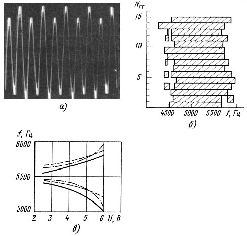
The graph of the dependence of the amplitude of parametric oscillations on frequency (Fig. 3.40) shows characteristic phenomenon- "pulling phenomenon" - for the region of loss of dynamic stability: a gradual increase in amplitude and a sharp break at the boundary of the region, and the nature of the amplitude changes with increasing and decreasing frequency is somewhat different. Since the maximum amplitude was reached at the upper boundary of the region for all investigated HGs, the dominant effect in the diaphragms of the HG is exerted by "nonlinear elasticity". It is interesting to note that for the excitation of subharmonic oscillations, some finite time of exposure to a signal of a certain frequency is required. With a fast passage of frequency at a speed of 5...7 s/oct, subharmonic oscillations are excited in much narrower frequency regions or are not excited at all.
Most often, subharmonic oscillations occur at values of about 0.8 P n (P n - rated power). In some rather rare cases, at high voltages, subharmonic oscillations with modulation, the so-called "beat mode", may occur in the GG. The spectrum of such a signal is shown in Fig. 2.10, oscillogram - in fig. 3.41. The theoretical description of the "beat regime" for complex elastic bodies, in particular thin elastic shells, encounters significant difficulties. Subjectively, this type of vibration is perceived as a strong overtone or bounce.

An analysis of the obtained theoretical dependencies, calculated data and a large amount of experimental research make it possible to establish the relationship between the characteristics of the parametric oscillations of diffusers with their design and physical and mechanical parameters and to identify the factors that have the greatest effect on reducing the level of overtones in the GG.
"Nonlinear elasticity" has a significant impact on the magnitude of the amplitude of parametric oscillations, and therefore on the likelihood of overtones, so all measures aimed at increasing the overall stiffness of the diffusers are extremely effective, since the resonant frequencies of the diffusers increase and the areas of "dynamic instability" shift in the higher frequency part of the spectrum, the amplitudes of parametric oscillations are significantly reduced. The greatest influence is exerted by an increase in the radius of curvature of the generatrix, the choice of the appropriate distribution of density and Young's modulus (due to the choice of materials and impregnations for diffusers that increase their rigidity), as well as the location of various stiffeners on the diffuser.
"Linear damping" due to internal friction in the material has a significant effect on the magnitude of the amplitude of parametric oscillations. Experiments have shown that an increase in the damping coefficient in the diffuser due to impregnation from 0.02 to 0.06 made it possible to reduce the amplitude of parametric oscillations by a factor of 7. In addition, the damping value determines the threshold level of the force required for the occurrence of parametric oscillations, i.e., the higher the damping decrement, the greater the applied voltage must be in order for this type of oscillation to occur at all. Increasing the damping in the system limits the phenomenon of "pulling" parametric oscillations beyond the instability regions, therefore, all measures aimed at increasing the internal damping in the diffuser (selection of impregnations, special materials, etc.) reduce the likelihood of overtones.
"Nonlinear damping" reduces the amplitude of parametric oscillations in proportion to A 1 ∼ 1/(Δ L) 0.5; where Δ L is the non-linear damping decrement. An increase in non-linear damping can be achieved by applying damping lubricants to the suspension, using appropriate materials for suspensions with high internal friction (rubber, rubberized fabrics, etc.). Experimental results show sufficient effectiveness of these means in reducing overtones.
"Nonlinear inertia" also contributes to an increase in the amplitudes of parametric oscillations, its reduction can be achieved by reducing the boundary masses (rational distribution of mass between suspensions, coil and diffuser) and increasing the rigidity of the suspension in the circumferential direction.
In conclusion, it should be noted that, as practice shows, a certain level of overtones is heard in the vast majority of serial GGs. An important task in the design of loudspeakers is the choice of such a combination of design and physical and mechanical parameters so that the level of critical load of diffusers P cr, below which the appearance of overtones of this type is unlikely, corresponds to the nominal or even maximum sinusoidal power of the loudspeakers, then when conducting any type of test GG overtones of this type will not be heard. If this fails, it is necessary to strive to increase the overall damping in the moving system in order to minimize the amplitude of parametric oscillations, i.e., the audibility of overtones.
Nonlinear processes associated with the Doppler effect in loudspeakers. characteristic feature electrodynamic GG is the occurrence of intermodulation distortions in them, due to both amplitude and frequency modulation of the signal. The distortions that determine the amplitude modulation of the emitted signals are due to the non-linearity of the elastic characteristics of the moving systems of the GG and the non-linearity of its electromagnetic parameters. The frequency modulation of signals that occurs in HG is associated with the Doppler effect. The latter is a long-known phenomenon in physics, which consists in the fact that in the presence of a source of oscillations with a frequency f 0 moving at a speed V 0 relative to a stationary receiver in a medium where c is the phase velocity of propagation of oscillations, a change in the wavelength and, accordingly, the frequency of the emitted oscillations: f = f 0 /. The processes that occur in the GG when it simultaneously reproduces a wide spectrum of frequencies and leads to the modulation effect of the low-frequency part of the spectrum on the high-frequency part are usually explained using the Doppler effect.
Methods developed in recent years for measuring AM and FM distortion have made it possible to quantify them in commercial loudspeakers. The nature of the frequency dependence of AM and FM distortion in a coaxial GG is shown in fig. 2.14. The frequency modulated signal can be written as follows:
p(t) = p m cos,
where p m is the amplitude of the emitted signal; f 2 - modulated (high) frequency, f 1 - modulating (low) frequency; m is the modulation index, ψ is the initial phase shift. Various criteria have been proposed to estimate the magnitude of Doppler distortion in HG, for example
where D is the distortion factor corresponding to the ratio of the power of the sidebands to the power of the modulated frequency, %; R A - acoustic output power at a frequency f 1 , W; d eff - effective diffuser diameter, mm. In addition, such a criterion is used as D = 1129f 2 /(1129 + X max πf 1), where X max is the maximum displacement amplitude, mm, etc. However, the choice of criteria for assessing FM distortion in the GG cannot be considered finally established. Despite a large set of works devoted to the study of the subjective assessment of Doppler distortions in HG, the results obtained are contradictory, since various methods and equipment were used. The following data on hearing thresholds can be considered pre-installed: on two pure tones no more than 1%, in music 8 ... 9%. In recent years, a physical interpretation of the Doppler effect has been proposed as a phase modulation of the emitted GH signal at the receiving point, which explains a number of previously obtained contradictory results.
Thus, despite many years of research devoted to the occurrence of nonlinear distortions in the HH due to the Doppler effect, significant issues remain unresolved that require additional analysis: the development of accurate quantitative criteria for calculating D in the HH and establishing their connection with the design parameters of diffusers; establishment of subjective perception thresholds D during the work of the HG, development of a promising methodology for their measurement in real HG and recommendations for their reduction.
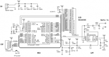
This article shows an original application of a small LCD graphics module. Last summer, the SG12232C LCD graphics module sold for 1500 yen and I bought it. But I couldn't find a good use for the LCD module, and I was going to send it to the junk box, so I tried to find some use for it.
Just displaying any still images is not cool, first I tried to display the sound waveform in real time as a digital oscilloscope, and then spectrum analysis with FFT. The spectrum monitor seems to be well done, given the implementation on a cheap microcontroller.
Hardware
The SG12232C is a full graphic LCD module with a resolution of 122(H)x32(V) dots. There are two Epson S1D15200 LCD controllers on the board. The S1D15200 can display up to 61(H)x32(V) dots and each drive half of the LCD. The SG12232C requires a 2 kHz square wave as a clock signal for the LCD and must be supplied while the power is on, otherwise the LCD may be damaged. You can choose a bus interface based on 8080 or 6800. There is no 4-bit mode like HD447880, only 8-bit mode is available and it requires at least 14 I/O lines.
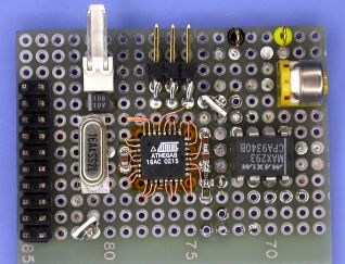
The image shows the assembled board and its circuit. An Atmel ATmega8 microcontroller is used, which digitizes the incoming audio signal and displays the waveforms on the LCD module. It's not hard to make. I used the MAX293, an 8th order elliptic filter, as the smoothing filter. The SCF is very useful and cheap compared to the discrete LPF.
Program
The image below shows the internal signal flow. The digitized data blocks are converted by FFT and displayed as bars in the left half (64 points) of the LCD. The waveform is displayed in the right half (58 points) with a cyclic shift of the signal.
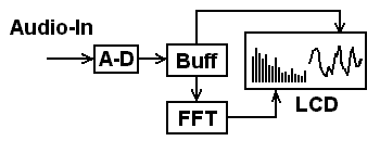
Operations are performed on a 16-bit fixed point. These 128 point FFT processes using intervals, butterfly operations and scalar output can be executed in real time (within 7.3ms). This is quite fast, given the processing by a cheap microcontroller. The division spectrum is displayed in the order of fundamental frequency x0 (DC), fundamental frequency x1, x2, x3, ... from left to right. The sampling rate is 9.6kHz and the fundamental frequency (frequency resolution) will be: 9.6k/128=75Hz.
There are also fixed point FFT libraries for the AVR-GCC. They are written in assembler and optimized for the megaAVR.
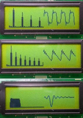
Here are some waveforms, square wave, sawtooth wave and sin(x)/x. You may find that they are displayed in the same way as in the tutorial.
List of radio elements
| Designation | Type of | Denomination | Quantity | Note | Score | My notepad |
|---|---|---|---|---|---|---|
| U1 | MK AVR 8-bit | ATmega8 | 1 | ATmega8-16AC | Search in Chip and Dip | To notepad |
| U2 | Chip | MAX293CPA | 1 | Search in Chip and Dip | To notepad | |
| C? | electrolytic capacitor | 10 uF | 1 | Search in Chip and Dip | To notepad | |
| C | Capacitor | 1 uF | 2 | non-polar | Search in Chip and Dip | To notepad |
| Capacitor | 100 nF | 5 | Search in Chip and Dip | To notepad | ||
| Capacitor | 22 pF | 2 | Search in Chip and Dip | To notepad | ||
| R1 | Resistor | 150 kOhm | 1 | Search in Chip and Dip | To notepad | |
| R2 | Resistor | 51 kOhm | 1 | Search in Chip and Dip | To notepad | |
| Resistor | 100 kOhm | 1 | Search in Chip and Dip | To notepad | ||
| Resistor | 20 kOhm | 1 | Search in Chip and Dip | To notepad | ||
| Resistor | 10 kOhm | 2 | Search in Chip and Dip | To notepad | ||
| Resistor |
The spectra are shown real and, since the signals in the mathematical sense are not ideal, the spectra differ from ideal ones (for example, for a square wave with a duty cycle = 2, even harmonics, although weakened, are noticeable. Or: for a sinusoidal, harmonics are visible, above the 1st ). However, the characteristic features in our case are quite obvious.
| 1. White noise. A complex oscillation in which ALL components are present AT ONCE. It's hard to believe, but such a signal contains ALL FREQUENCIES, and their power is the SAME, so the spectral envelope is horizontal. Really white noise in nature is probably difficult to find. |  ALL frequencies in the spectrum. |
|
| 2. Sinusoidal oscillation. Simple, "natural", soft to the ear. It is rarely found in its pure form in nature. The closest sounds are: the vowel "U", the sound of a flute, whistling, when these sounds are produced at an average volume, without strain, i.e. with a minimum content of high components. | 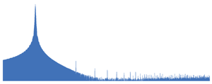 There is one harmonic / frequency component in the spectrum. |
|
| 3. Rectangular (meander), duty cycle =2*. A complex oscillation in which all even harmonics are ABSENT. From musical instruments the closest thing to a similar form is the sound of a clarinet, with such a characteristic "trumpet", "emptiness". | 
|
* duty cycle is the ratio of the pulse repetition period ( T ) to the pulse duration ( t ). In the English-language literature on electronics, the term is more often used fill factor (D=t/T ), inversely proportional to the duty cycle.
| 4. Sawtooth oscillation. A complex oscillation in which ALL HARMONICS are present. Of the musical instruments, the sound of stringed bowed instruments is closest to a similar form when extracted with a bow. Also, a similar form is produced vocal cords person. | 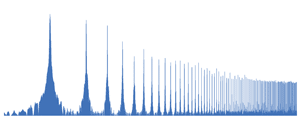 In the spectrum of harmonics 1,2,3,4,5,6,7,8,9 ... etc. |
|
| 5. Triangular oscillation. A complex oscillation in which all even harmonics are ABSENT, but unlike the square wave, the amplitudes of the harmonics decrease faster with increasing number. From musical instruments, the sound of ONE organ pipe is closest to this form. It sounds a little sharper than a sinusoidal one. | 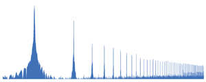 In the spectrum of harmonics 1,3,5,7,9, ... etc. |
|
| Everything is the same as with white noise, the only difference is that the amplitudes of the frequency components decrease uniformly with increasing frequency. Therefore, the envelope of the spectrum is a straight sloping line, and this noise is softer by ear (more low, and less high) than white. |  ALL frequencies in the spectrum. |
|
| 7. Rectangular, duty cycle =4. A complex oscillation in which all harmonics that are multiples of 4 are ABSENT. |  In the spectrum, all harmonics, except for 4,8,12,16 ... etc. |
|
| 8. 2 sinusoidal oscillations. Complex, including the 1st and 2nd harmonics. Soft to the ear with a clearly distinguishable octave overtone (2nd harmonic). | 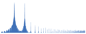 There are 2 harmonics in the spectrum - 1st and 2nd. |
|
| 9. 2 sinusoidal oscillations. Complex, including the 1st and 3rd harmonics. Soft to the ear with a clearly distinguishable fifth overtone. The 3rd harmonic is a pure fifth through an octave. | 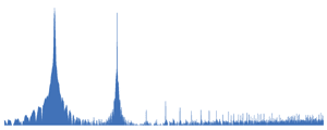 There are 2 harmonics in the spectrum - 1st and 3rd. |
Page 2
Most often, F, during acoustic reproduction of the transmitted signal, is heard in the form of a relatively low humming overtone.
In conclusion, it should be noted that, as practice shows, a certain level of overtones is heard in the vast majority of serial GGs.
Distortions of the first type are the result of excitation in the diffuser material of the so-called structural overtone, which has a more or less uniform spectrum. Such distortion is most significant in an underdamped cone and occurs as a response to mechanical excitation, the source of which is the voice coil. This type of distortion gives the loudspeaker the characteristic tonal coloring characteristic of this type of loudspeaker. Distortions of the second type depend on the intensity of standing waves arising in the diffuser, the cause of which was discussed above. Intense standing waves lead to the formation of diffuser sections capable of emitting sound at natural frequencies. The emissions of the diffuser sections are also classified as non-linear distortions, and they can be several times higher than the first type of distortions. From here, the way to combat such distortions becomes obvious, which consists in reducing the intensity of the component of mechanical vibrations reflected from the diffuser holder and ensuring the traveling wave mode in the diffuser. Diffusers of high-quality loudspeaker heads are usually made with a glued top suspension and a collar, made separately from a material with a high damping index of mechanical vibrations. These heads have more high cost and less technologically advanced in production compared to mass-produced loudspeaker heads, the diffuser of which is manufactured together with the upper suspension and collar. Another drawback of heads with a glued top suspension is their lower sensitivity, due to the lower radial rigidity of the glued suspension and the risk of rubbing the voice coil in the gap. This danger forces designers to use a wider air gap with a corresponding reduction in magnetic field strength. The cause of voice coil mashing is the helical winding of its coils and the associated tangential component of the Lorentz force. In low-frequency loudspeaker heads, the use of a particularly flexible upper suspension allows, in addition to attenuating the mechanical vibrations reflected from the diffuser holder, to obtain a lower resonant frequency. For mass broadband and mid-frequency loudspeaker heads, a decrease in the intensity of the components reflected from the diffuser holder and the provision of a traveling wave mode can be achieved by applying vibration-absorbing non-drying mastic to the part of the upper suspension that is not included in the dynamic mass of the diffuser.
Sometimes, when working out timbres, a sharp creaky overtone appears in the musical tone in some parts of the full range of sounding, which is explained by the appearance of new pronounced odd harmonics in the sound spectrum, separated by a large frequency band.
The purpose of the exercise is to develop the skill of maintaining a fixed apical-alveolar barrier for two final consonants without intermediate overtones. In combinations of sonants, the explosion of difficulties, as a rule, does not occur, but the position of the explosive in front of the sonant often causes breakdowns of the tongue due to excessive muscle tension. Gradually, the articulations become more plastic and breakdowns of the obstruction are eliminated. It is necessary to follow the rules for vowel length and other previously given instructions.
To reduce the vibrations of individual acoustic design panels that occur at their resonant frequencies during the operation of the loudspeaker and generate overtones that distort the main sound, various vibration-absorbing materials are used.
The flaccidity of tone when pronouncing [ d ] is especially important in final positions, where a tense explosion often causes vowel overtones that are alien English pronunciation. The features of articulation of English voiceless and voiced are valid for all categories of consonants. Comparison of words with voiceless and voiced final consonants should also be used for contrast training of quantitative changes in vowel sounds: their reduction before voiceless and lengthening before voiced.
Oe ti: tfa] teacher, as well as with vowels and, y, when they are pronounced with a consonant overtone [ j ]: the union [ Ze ju: njan ] union, the year [ Ze e: ] year.
In most GGs with mechanical defects, when excited by a monoharmonic signal, a specific sound is heard at some frequencies, perceived as an overtone, simultaneously with rattling. In the proposed method of differentiated evaluation, which allows to objectively separate the overtone from the rattling. It is based on the difference in the spectral characteristic: the rattling differs from the overtone in the different energy distribution of the discrete spectrum of harmonics in the pulse signal. For overtones, it is characteristic that the main part of the energy of the pulse signal is concentrated in one or three harmonics, for rattling - more than four. In the time domain, the differences are that the damped oscillatory process of the overtone has a duration of more than half the period of the excitation signal; rattling has a duration less than half.
SPECTRUM OF SOUND
SPECTRUM OF SOUND
Expresses the frequency composition of the sound and is obtained as a result sound analysis. S. h. usually represent on the coordinate plane, where the frequency is plotted along the abscissa f, along the y-axis - amplitude BUT or intensity I harmonic component of the sound. Pure tones, sounds with periodic. shape, as well as sounds obtained by adding several. periodic waves, have line spectra(Fig. 1). Acoustic , single impulses, decaying sounds have a continuous spectrum (Fig. 2). Frequency spectrum acoustic pulse rectangular carrier-filled shapes f 0 concentrated in the main near this frequency in a band of width 1/T, where T - pulse duration.
Lit. see at Art. Sound.
Physical encyclopedia. In 5 volumes. - M.: Soviet Encyclopedia. Editor-in-Chief A. M. Prokhorov. 1988 .
See what "SOUND SPECTRUM" is in other dictionaries:
The set of simple harmonic waves into which one can decompose sound wave. S. h. expresses its frequency (spectral) composition and is obtained as a result of sound analysis. S. h. are usually represented on the coordinate plane, where along ... ... Great Soviet Encyclopedia
spectrum of sound- garso spektras statusas T sritis fizika atitikmenys: engl. auditory spectrum; sound spectrum vok. Klangspektrum, n; Schallspektrum, n rus. sound spectrum, m; sound spectrum, m pranc. spectrum acoustic, m; spectrum du son, m; spectre sonore, m … Fizikos terminų žodynas
spectrum of sound- garso spektras statusas T sritis Standartizacija ir metrologija apibrėžtis Sudėtinio (kelių tonų) garso skirtingų amplitudžių ir dažnių harmoninių virpesių visuma. atitikmenys: engl. acoustic spectrum; sound spectrum vok. akustisches Spektrum, n; … Penkiakalbis aiskinamasis metrologijos terminų žodynas
SPECTRUM OF SOUND- (from lat. spectrum visible, vision ...) an objective characteristic of a sound of a complex composition, reflecting its internal physical structure (as opposed to an external structure reflected by a waveform or an oscillogram). S. h. graphically... ... Encyclopedic Dictionary of Psychology and Pedagogy
Spectrum of sound- a set of simple harmonic waves into which a complex sound wave can be decomposed. To obtain the S. of any sound means to obtain the totality of the amplitude values of all the frequency components that form the given sound. Such a S. is called ... ... Pedagogical speech science
Spectrum of sound (light)- sound (light) spectrum: intensity or sound pressure level in relation to sound (light), which is a function of frequency or wavelength ... Source: GOST R 51340 99. State standard Russian Federation. Machine safety... Official terminology


 Английский вокруг нас исследовательская работа")
