Basic concepts and an example of doing independent work
linkage
Lever mechanism - a mechanism, the links of which form only rotational, translational, cylindrical and spherical pairs. An example of a lever mechanism is a cam-lever mechanism - a device that is a connection of lever mechanisms with cam mechanisms. Such connections are made in two versions:
1) consistent;
2) parallel.
In most cases, the cam-lever mechanism is understood as parallel connections. Cam-lever mechanisms are used to change the lengths of links of lever mechanisms during the movement and, accordingly, obtain the specified laws of motion and improve performance. Lever mechanisms are most widely used in combination with gear mechanisms or gear-lever mechanisms. This type of mechanisms are devices containing gear and lever mechanisms interacting with each other, and their connections can be serial or parallel.
In various machine tools, machines and automatic control systems in engineering industries, mainly parallel-connected gear-lever mechanisms are used. In particular, the so-called Roman gear is used - a seven-link mechanism with a slider driven through a summing lever and two connecting rods from two gears meshing with each other. In such a mechanism, either a lever or a gear can be either a drive or a slave. Gear-lever mechanisms in a number of variants usually contain two pairs of interacting gears, one of which is connected with a link of the lever mechanism. In general, gear-lever mechanisms make it possible to obtain various laws of movement of links, to improve power characteristics the whole mechanism. In most cases, gear-lever mechanisms are used as guides and transmission mechanisms (especially in automatic machine lines used in many branches of the industrial and economic complex of Russia).
author Team of authorsClamshell mechanism The clamshell mechanism is a device for cyclic pulling of a perforated tape (in particular, films in movie projectors or in movie cameras). Such a mechanism performs intermittent unidirectional movement. As a clamshell mechanism
From book Big Encyclopedia technology author Team of authorsGear mechanism A complex gear mechanism is a device with gears, in which more than two gears participate. Devices can be developed both as a kind of structural technology, and with the help of sequential,
From the book Great Encyclopedia of Technology author Team of authors From the book Great Encyclopedia of Technology author Team of authorsCam mechanism A cam mechanism is a mechanism that includes a cam. In various sectors of the industrial and economic complex of Russia, cam mechanisms are widely used in different versions. Option one: in the mechanism, the cam has a working
From the book Great Encyclopedia of Technology author Team of authorsRocker mechanism The rocker mechanism is a lever mechanism, which includes a rocker. In various machines, machine tools and other equipment are widely used different kinds rocker mechanism: 1) rocker-slider mechanism; 2) crank-rocker
From the book Great Encyclopedia of Technology author Team of authorsMechanism A mechanism is a system consisting of several elements (or links) and designed to convert the movement of one or more solid elements into the required movements of other elements of this system. Mechanisms are characterized by: 1) mechanical
From the book Great Encyclopedia of Technology author Team of authorsLever mechanism A lever mechanism is a mechanism, the links of which form only rotational, translational, cylindrical and spherical pairs. An example of a lever mechanism is a cam-lever mechanism - a device that is a connection
From the book Great Encyclopedia of Technology author Team of authorsFolding mechanism The folding mechanism is a device designed to fold a sheet of paper and is widely used in printing work. This mechanism functions as follows: a sheet of paper moves when the feed cylinder rotates in
From the book Great Encyclopedia of Technology author Team of authorsFriction mechanism A friction mechanism is a device in which the transmission of motion, acceleration or braking is carried out due to the forces of friction between the elements pressed against each other. In a friction mechanism consisting of rigid elements (in a transmission, clutch,
6.1. Statement of the problem, types and methods of synthesis
The problems of synthesis of lever mechanisms in the general case are complex problems of optimal design, including the stages of structural, kinematic and dynamic calculation. Therefore, to simplify the solution, particular problems are considered, in which only some (basic) design conditions are taken into account.
Depending on the initial data, the following types of synthesis are distinguished:
Geometric, when individual positions of links or trajectories of individual points are given;
Kinematic, when certain speeds, accelerations or their ratios are given;
Dynamic, when the acting forces are given or some restrictions are imposed on the dynamic parameters.
Synthesis methods include:
a) experimental, when the dimensions of the links are selected experimentally to implement a given trajectory;
b) graphic;
c) analytical.
Various combinations of the types and methods of synthesis listed above are possible.
6.2. Solving problems of optimal synthesis of rod mechanisms
When setting the problem of optimal synthesis, one should distinguish between input and output parameters.
Input parameters are initially set parameters (link sizes, speeds, accelerations or their ratios).
The output parameters are the parameters determined as a result of solving the problem.
When synthesizing, it is necessary to take into account a number of requirements of a kinematic, constructive, technological nature, etc., among which one, as a rule, is the main one, and the rest are secondary (additional). If the main requirement is written mathematically as a function , where  - output parameters, then such a function is called goal function(target), while additional conditions, expressed as , are called restrictions.
The task of optimal synthesis is to provide an extreme value of Z, subject to all restrictions.
For example, by expressing the weight of a mechanism as a function Z of its parameters (link lengths), one can solve the problem of minimizing Z under the conditions for its existence. These conditions include the conditions for turning the crank in a articulated four-bar linkage, the condition for maintaining a given pressure angle, and a number of others.
With a small number of output parameters, the solution of the optimization problem can be obtained in an analytical form. Otherwise, numerical methods of directed, random or combined search for optimal solutions are used.
6.3. Conditions for crank rotation in a four-link articulated link
P  When designing (synthesising) a four-hinged mechanism, one of the conditions to be taken into account may be the crankability of the links, that is, the presence of one or two cranks. It depends on the ratio of the lengths of the links. For example, in order for the AB link of a four-link link (Fig. 37) to become a crank, it must sequentially pass through two extreme positions. Using the three positions of the mechanism, we obtain the following conditions:
for positions 1, 2, 3, having previously indicated the lengths of the links:
Wherein:
that is, the sum of the lengths of the crank and any other link is less than the sum of the remaining links.
We add the pairwise obtained inequalities and get:


 , that is, the crank is the shortest link. And if these conditions are not met, then the mechanism will be either two-crank or two-rocker. These conditions are used in geometric synthesis.
Federal Agency for Education
State educational institution higher professional education
"MATI" - Russian state University of Technology named after K.E. Tsiolkovsky
Department of “Mechanics of machines and mechanisms”
FORCE CALCULATION OF LEVER MECHANISMS
Guidelines for course design on the theory of mechanisms and machines
Compiled by: Chufistov V.A. Shuvalova L.S.
Moscow 2006
1. OBJECTIVES AND CONTENT OF FORCE CALCULATION
The power calculation of mechanisms consists in determining all the forces and moments of forces applied to each link of the mechanism. The magnitude, direction and points of application of forces acting on links and kinematic pairs must be known for subsequent calculations of strength, wear resistance, reliability and for solving other problems of designing mechanisms. When the mechanism is operating under the action of all external forces applied to its links, as well as as a result of the uneven movement of its links in kinematic pairs reaction forces arise, i.e. interaction forces between links. The reaction forces in the force calculation are determined to assess and ensure the operability of the mechanism, in particular for the selection and calculation of bearings.
The main task of the force calculation is to determine the reaction in the kinematic pairs of mechanisms, as well as to determine the balancing force or pair of forces (balancing moment) and engine power.
Force calculation can be performed with or without friction forces. In most mechanisms, losses to overcome friction are small, and neglecting them makes it possible to significantly simplify and shorten the calculation. Kinetostatic calculation can be performed by the method of force plans or by the method of Professor N.E. Zhukovsky.
In the course project, the kinetostatic calculation of the mechanism is performed for one given position of the mechanism in both ways. The results obtained are compared, and the discrepancy should not exceed 5%.
2. FORCE CALCULATION ACCORDING TO THE METHOD OF FORCE PLANS
2.1 General information.
The kinetostatic method of force calculation is based on the d'Alembert principle, according to which the equations of statics can be applied to a system moving with acceleration if dynamic loads are added to the static loads acting on the system. Static loads depend on the weight of the links G i , useful and harmful resistances F . Dynamic
loads depend on masses G g i , moments of inertia of links I si , linear
accelerations of the mass centers of links a si and angular accelerations of links ε i .
The dynamic load of any link of a flat mechanism is reduced to its center of gravity and, in the general case, consists of the main vector and the main moment of inertia forces. The modulus of the inertia force of a link performing a plane-parallel motion or non-uniformly rotating around a fixed axis is calculated by the formula:
where I si is the moment of inertia of the link relative to its center of gravity. The moment is directed in the direction opposite to the angular acceleration of the link M H i → − ε G i .
In the absence of friction forces, it is assumed that the reaction in the translational kinematic pair is perpendicular to the guides. If the center of mass
of the slider coincides with the hinge, by which the slider is connected to the rod link, the reaction passes through the hinge, and the calculation task is to find the magnitude of the reaction. If the center of mass of the slider does not coincide with the hinge, the calculation task is to determine the magnitude of the reaction and its point of application. The reaction in the rotational kinematic pair is applied in the center of the hinge and the task of calculation is to determine its magnitude and direction. Sometimes it is advisable to represent such a reaction in the form of two components, one of which is directed along the link and is called the normal component, and the other is perpendicular to it and is called the tangent component. It is customary to designate the reaction applied to the “k” link from the side of the “i” link, R ik , and the components of the reaction
R n ik and R τ ik.
2.2 Initial data
Mechanism plan.
Angular rotation speed ω .
Crank position coordinate ϕ deg.
The positions of the centers of mass of S i links.
Weights G i and moments of inertia of links I si .
Useful resistance force (cutting force) F .
2.3. The sequence of power calculation.
The following order of force calculation is established without taking into account friction forces in kinematic pairs.
2.3.1. We draw a plan of the mechanism for a given position of the crank
in selected scaleμ l .
2.3.2. We apply the weights of the links G i in the centers of mass S i and the useful resistance force F to the slider. All forces are depicted without scale as vectors of the same length (15 - 20 mm).
2.3.3. We build a plan of accelerations on a scale of μ a m / (s2 mm). It is advisable to transfer the mechanism plan and the acceleration plan from the first sheet. Using the rule of similarity, on the plan of accelerations we find the vectors representing the accelerations of the centers of mass of the links and by the formula
a si | = πS i μa ( | ||||
we calculate the magnitudes of the accelerations themselves. According to formula (1), we determine the inertia forces of the links, apply them at the centers of mass of the links, directing them in the opposite direction to the vector a si .
We find the magnitudes and directions of angular accelerations for the corresponding links:
εi= | a ti | |||
according to the formula (2) - the moments of inertia forces for the same links and in the form of a circular arrow we apply them to the links. In this case, it must be remembered that the moment of inertia forces is directed in the opposite direction to the angular acceleration of the link
(so for the mechanism 2 ε 4 = 0 and M 4 = 0 ). On fig. 1a the plan of the mechanism is built
1 with static and dynamic loads applied to its links, in fig. 1b is his acceleration plan. Accordingly, for mechanism 2, the plan of the mechanism and the plan of accelerations are plotted in Fig. 2a,b, for mechanism 3 - in fig. 3a,b and for mechanism 4 - in fig. 4a,b


2.3.4. We disconnect from the mechanism a structural group consisting of links 4 and 5. For mechanisms 1,3 and 4, this is the dyad 2 of a particular modification (Figures 5a, 7a). In mechanisms 1 and 4, slider 5 moves along a horizontal guide and its center of mass S 5 does not coincide with hinge E. In mechanism 3
slider 5 moves along a vertical guide and its center of mass S 5
coincides with hinge E. Dyad 4-5 will be in equilibrium if reactions from the side of the discarded links are applied to it - reaction R 65 from the side of the rack 6 to the slider 5 and reaction R 34 from the backstage 3 to the connecting rod 4. Reaction
tangential component R τ 34 | perpendicular to link 4. |
||||||
The magnitude and direction of the reaction | R τ34 | determine if we make an equation |
|||||
of all forces applied to link 4 relative to hinge E: |
|||||||
Σ Μ (4 stars) = Ο → R τ 34 ; | |||||||
h + G h− | M 4 − R τ | DE = 0 . | |||||
R τ = U 4 h 1 + G 4 h 2 − M 4 | μ l . | ||||||
In equation (7) the forces are substituted in N, the arms of the forces in mm, the moment of inertia Μ 4 in Nm, the scale of the dyad plan -μ l in m/mm. If the answer is negative, the direction of the reaction Rτ 34 must be reversed.
Reactions Rn 34 and R65 can be found from vector equation sum of forces applied to dyad 4-5.
RG τ | +(F G +U | )+R | ||||||||
Lever mechanisms with lower kinematic pairs are widely used in modern mechanical engineering. The advantages of such mechanisms include: high manufacturability, the possibility of using rolling bearings in kinematic joints, the possibility of transferring large forces with little wear on the contacting surfaces, reliability and durability in operation. These mechanisms do not require devices that ensure the constant closure of kinematic pairs, unlike cam mechanisms.
Mechanisms are created from the conditions of meeting the requirements of the technological process. The design of mechanisms is a complex task, the solution of which can be divided into two stages. First stage The synthesis of mechanisms consists in choosing a kinematic scheme that provides the required form and law of motion of the output link and the general conditions for the operability of the mechanisms. In second stage constructive forms of links and kinematic pairs are developed to ensure the strength and reliability of the mechanism. Our course covers only first stage synthesis.
The scheme of the mechanism, as a rule, is selected on the basis of experience, in relation to these specific conditions. Then determine synthesis parameters, i.e. lengths of links and coordinates of points that provide the required trajectories, etc., as well as additional synthesis conditions.
Additional synthesis conditions include crank existence condition, as well as transfer condition.
Force transfer condition
It is customary to characterize the quality of force transfer in machines by the pressure angle λ, determined without taking into account the gravity forces of the links and the forces of inertia.
pressure angle λ is an acute angle between the vector of the force acting on the driven link from the side of the movable link adjacent to it, and the vector of the absolute velocity of the point of application of this force.
Motion Transmission Angle γ complements the pressure angle up to 90°:
γ = 90° - λ .
At the stage of metric synthesis, the maximum permissible angles of pressure [λ max ] and transmission of motion [γ min ] are limited, as a rule, taking them:
[λ max ] ≤ 30° and [γ min ] ≥ 60° for a linear driven link, and
[λ max ] ≤ 40°...45° and [γ min ] ≥ 50°...45° for a rotating driven link.
Consider the condition for the transfer of forces in a hinged four-link, which is in equilibrium under the action of the moments of the driving M D and moment of resistance M C (Fig. 3.1). The pressure angle λ characterizes the ratio between the useful drag force F 23 cos λ overcoming the moment of resistance M With, and force F 23 equal to
F 23 = M FROM /( l sun cos λ).
Fig.3.1. Angle λ of pressure in a hinged four-bar
As the angle of pressure increases, more force must be applied F 23 to overcome the same moment of resistance. This leads to an increase in reactions in kinematic pairs and a decrease in the efficiency of the mechanism.
As the mechanism moves, the pressure angle changes. This angle in the hinged four-link reaches extreme values in positions when the crank OA located on the same line with the rack OS(Fig. 3.2).

Fig.3.2. Positions of the mechanism at which the pressure angles reach
extreme values
In the crank-slider mechanism, the pressure angle acquires extreme values in the positions indicated in fig. 3.3 when the crank OA perpendicular to the trajectory of the slider AT.

Rice. 3.3. Positions of the mechanism at which the pressure angles
have extreme values.
The tasks of kinematic synthesis of mechanisms that are most frequently encountered in course projects are considered below.
Synthesis of a hinged four-link by the coefficient of change average speed and two extreme positions of the rocker arm
Coefficient k changes in the average speed of the driven link is equal to k = V C 2 – 1 / V C 1 – 2 ,
where V C 1 – 2 − point mean line speed FROM(Fig. 3.4) during the working stroke, V C 2 – 1 − the same for the reverse.
Accept k> 1, since when designing mechanisms, as a rule, the return time to the initial position is taken less than the working stroke time, therefore k > 1.
It is easy to prove that k= (180° + θ) /(180° - θ).
From where θ = 180° ( k −1) /(k +1),
where q − angle between connecting rod positions BC at the beginning and at the end of the workflow.
Let us introduce the notation:
l 1 - crank length AB,(see fig. 3.4); l 2 - connecting rod length sun;
l 3 - the length of the rocker CD; l 4 - distance between supports (rack length BUTD).

Rice. 3.4. Scheme of the mechanism in positions corresponding to the values of the given angles ψ
Given the angles ψ 1 and ψ 2 , as well as the coefficient k, depict two extreme positions of the rocker CD(Fig. 3.5).
points FROM 1 and FROM 2 connect with a straight line. Calculate the angle q between the extreme positions of the connecting rod sun. At point FROM 2 construct an angle γ = 90° −
θ, and from the point FROM 1 lower the perpendicular to the line FROM 1 FROM 2 to the intersection with the line drawn from the point FROM 2 and forming the angle γ. We denote the point of intersection of these lines O. Obviously, in a right triangle OFROM 1 FROM 2 corner FROM 1 OS 2 = θ. Three points O, FROM 1 and FROM 2 describe a circle. Inscribed angle with vertex at a point O leans on the arc  and is equal to the angle θ, as well as all inscribed angles based on the same arc. We choose on a circle centered at a point O arbitrary point BUT and connect it with straight segments with points FROM 1 and FROM 2. As a result, by placing the crank support at the point BUT, we get a diagram of a four-link mechanism in extreme positions (see Fig. 3.5).

Rice. 3.5. Synthesis of a hinged four-link by the coefficient k
changes in average speed and two extreme positions of the rocker
It follows from the figure AC 1 = AT 1 FROM 1 −AB 1 = l 2 − l 1 ; AC 2 = AT 2 FROM 2 −AB 2 = l 2 + l 1 .
Where l 1 = 0,5 (AC 2 −AC 1) μ l / 2; l 2 = AC 2 − l 1 .
Stand length BUTD = l 4 will be determined by the position of the point BUT.
Since the position of the point BUT was chosen arbitrarily, there is a multivariance of the solution of the problem. This allows you to enter additional conditions, for example, the condition for the transfer of forces, the presence or absence of eccentricity of the location of the supports with respect to the coordinate axis.
Synthesis of the rocker mechanism according to coefficientk changes
medium speed backstage
Given: coefficient k changes in travel speed and two extreme positions of the point AT backstage sun.
Consider the rocker mechanism in two extreme positions (Fig. 3.6).
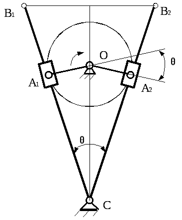
Rice. 3.6. Synthesis of the rocker mechanism
Angle between crank position OA 2 and the continuation of the crank in position OA 1 equals θ = 180° ( k −1) /(k+1). corners AT 1 M B 2 and q will be equal to each other, like angles with mutually perpendicular sides.
On a straight line AT 1 AT 2 we build an isosceles triangle with an angle at the vertex FROM equal to the angle q. On the straight line dividing the angle q in half at an arbitrary point, choose a point O around which the crank rotates OA. dropping from the point O perpendicular to a line AT 1 FROM(or AT 2 FROM), find the length of the crank OA. The resulting rocker mechanism will satisfy the given conditions. The construction of the rocker mechanism according to the given conditions is as follows. points AT 1 and AT 2 , whose position is given, we will connect with a straight line.
Synthesis of a crank-slider mechanism
We accept the following conventions (Fig. 3.7):

Rice. 3.7. Scheme of the crank-slider mechanism
r- crank length OA;H- slider stroke; l- connecting rod length AB;
e– deaxial, i.e. point path offset AT slider about the axis Oh ;
L = l/ r- the relative length of the connecting rod;
ν = e/r– relative deaxial;
h = H/ r- relative stroke of the slider ;
λmax is the maximum pressure angle (see Fig. 3.3);
k − coefficient of change in the average speed of the slider (see § 3.1)
ψ 1 and ψ 2 – sharp corners formed by the crank OA with direction Oh in the extreme positions of the slider: φ 1 =  AT 1
Oh, φ 2 = AT 2
Oh
;
AT 1
Oh, φ 2 = AT 2
Oh
;
θ \u003d ψ 2 - ψ 1 - an acute angle between the connecting rods in the extreme positions of the slider.
Task 1. Given: Not, L = l/ r.
Find: r; l; ׀λ max ׀.
crank length OA: r = H / h. Connecting rod length AB: l = L r.
The greatest value of the pressure angle ׀ λ max ׀ = arc sin [(1 + ν) / L] .
Task 2. Given: H,k, L= l/ r.
Find: r; l; e; ׀ λ max ׀.
Acute angle between the connecting rods in the extreme positions of the slider
θ = 180 0 ∙( k–1)/(k+1).
We find the relative stroke of the slider from the expression
h = {2∙} 0,5 .
We find the relative deaxial from the expression
ν = [( h –2)∙(L 2 –1)] 0,5 .
crank length r = H/ h; connecting rod length l = L r; desaxial e =ν r.
The greatest value of the pressure angle λ max = arc sin [(1 + ν) / L].


 Английский вокруг нас исследовательская работа")
